Panoramic image acquiring system

A collection system and panoramic image technology, applied in image communication, TV system components, TV, etc., can solve the problem of image processing modules that are difficult to use together, image color temperature, brightness and darkness, and other imaging effect differences, attitude, and position out of sync and other issues to achieve the effect of simplifying data acquisition tasks and panorama stitching tasks, reducing the number of chips and lenses, and reducing difficulty and cost

Active Publication Date: 2015-12-02
成都易瞳科技有限公司
View PDF7 Cites 26 Cited by
  • Summary
  • Abstract
  • Description
  • Claims
  • Application Information

AI Technical Summary

Problems solved by technology

The field of view of the multi-channel lens covers a field of view greater than 360 degrees. Although it is possible to collect panoramic images, since multiple different sensors are used to independently collect images in different fields of view, the sensitivity parameters of multiple sensor chips are different. There are differences in imaging effects such as color temperature, brightness and darkness in images collected by different sensors. In addition, since the image signals collected by multiple sensor chips cannot be synchronized well, it will also lead to the same moving object being imaged on different sensors. The posture and position in the center are not synchronized.
[0003] At the same time, multi-sensor applications have high requirements for back-end image processing chips, not only requiring at least two channels of video input and screen synchronization, but also high requirements for hardware interfaces, drivers, computing power and other indicators. Currently, such processing chips on the market The cost of the device is generally relatively high, and the development difficulty and cost are also relatively high, and it is difficult to cooperate with the existing image processing module; at the same time, the module requires multiple sensors and lenses, which increases the cost of additional modules

Method used


Image

  • Panoramic image acquiring system
  • Panoramic image acquiring system
  • Panoramic image acquiring system

Examples


Embodiment Construction

[0022] The present invention is specifically described below through the examples, the examples are only used to further illustrate the present invention, and cannot be interpreted as limiting the protection scope of the present invention, some non-essential improvements made by those skilled in the art according to the contents of the present invention And adjustments also belong to the protection scope of the present invention.

[0023] combine Figure 1 to Figure 4 .

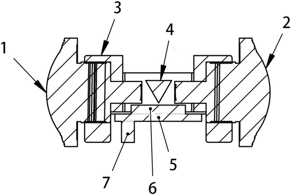
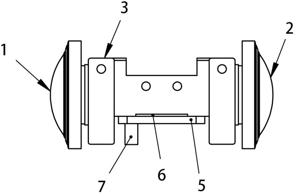
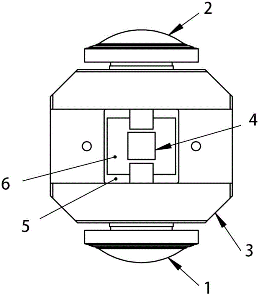
[0024] The panoramic image acquisition system includes a fisheye lens module, an image sensor 6 and a signal transmission line. There are two groups of the fisheye lens module, which are respectively the fisheye lens module 1 in the front field of view and the fisheye lens module 2 in the rear field of view, The optical axes of the two groups of fisheye lens modules overlap each other and are relatively arranged at both ends of the same optical axis. A prism 4 is arranged in the center of the line connecting...


PUM


Abstract

The invention discloses a panoramic image acquiring system. The system comprises two fish eye lens modules, an image sensor and a signal transmitting line. The optical axes of the fish eye lens modules overlap with each other and the fish eye lens modules are oppositely arranged at two ends of the same optical axis; a prism is arranged at the center of a connecting line connecting the optical centers of the two fish eye lens modules. The image sensor is arranged below the prism. Imaging optical signals of the two fish eye lens modules are projected to the reflection planes at two sides of the prism respectively, and after reflection, a left image and a right image are formed on the same target surface of the image sensor. With the panoramic image acquiring system, complete unification of image qualities and complete synchronization of images of different fields in a panoramic image can be realized. As only one video output channel is adopted, the data collection task and panoramic splicing task in post-processing of a panoramic image can be greatly simplified, and therefore, difficulty and cost are reduced. Further, the number of image sensor chips and the number of lenses are reduced, and the cost of the image acquiring system is reduced. Images obtained from the system are higher in quality and image quality is more stable.

Description

technical field [0001] The invention relates to a panoramic image acquisition technology, in particular to a technology for realizing the acquisition and processing of a full-heaven spherical panoramic image. Background technique [0002] At present, the widely used panoramic image acquisition device is obtained by separately collecting images in different angles of view by multi-channel sensors. Usually at least two image sensors are required, and the mainstream uses are two-channel, three-channel, four-channel, five-channel, Six-way or even more to get panoramic images. The field of view of the multi-channel lens covers a field of view greater than 360 degrees. Although it is possible to collect panoramic images, since multiple different sensors are used to independently collect images in different fields of view, the sensitivity parameters of multiple sensor chips are different. There are differences in imaging effects such as color temperature, brightness and darkness i...

Claims


Application Information

Patent Timeline
Patent Type & Authority Applications(China)
IPC IPC(8): H04N5/232G03B37/00
Inventor 张恩泽赖文杰胡志发成茵余黎
Owner 成都易瞳科技有限公司
Why Eureka
Try Eureka