

error handling system
An error handling and error technology, applied in general control systems, control/adjustment systems, test/monitoring control systems, etc., can solve problems such as error code increase
- Summary
- Abstract
- Description
- Claims
- Application Information
AI Technical Summary
Problems solved by technology
Method used
Image

Examples
Embodiment approach 1
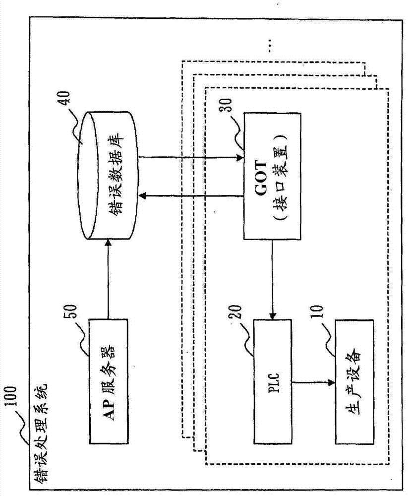
[0049] figure 1 It is a block diagram of the error processing system 100 of Embodiment 1.
[0050] The error processing system 100 is a system that performs processing related to errors occurring in the production equipment 10 constituting the FA system. The error processing system 100 is provided with the production facility 10, PLC20, GOT30 (an example of an interface device), the error database 40, and the AP server 50 (application server).
[0051] There are a plurality of production facilities 10 , and PLC 20 and GOT 30 are provided for each production facility 10 . Between the production equipment 10 and the corresponding PLC20, between the PLC20 and the corresponding GOT30, between each GOT30 and the error database 40, and between the error database 40 and the AP server 50 are respectively connected via a network. The communication traffic between each GOT30 and the error database 40, and the network between the error database 40 and the AP server 50 may be limited to...
Embodiment approach 2
[0081] In Embodiment 2, the method which can perform maintenance of an error message efficiently is demonstrated.
[0082] In Embodiment 2, the description will focus on parts different from Embodiment 1. FIG.
[0083] When shifting to unified management of data based on the error database 40 , it may be registered in the error database 40 sequentially while checking the data stored in each GOT 30 . However, in the FA system, production of products is prioritized, and operators are so busy that they hardly care about the fact that the processing related to error messages is true. Therefore, a configuration is required to preferentially register error messages that really need to be registered in the error database 40 in the error database 40 .
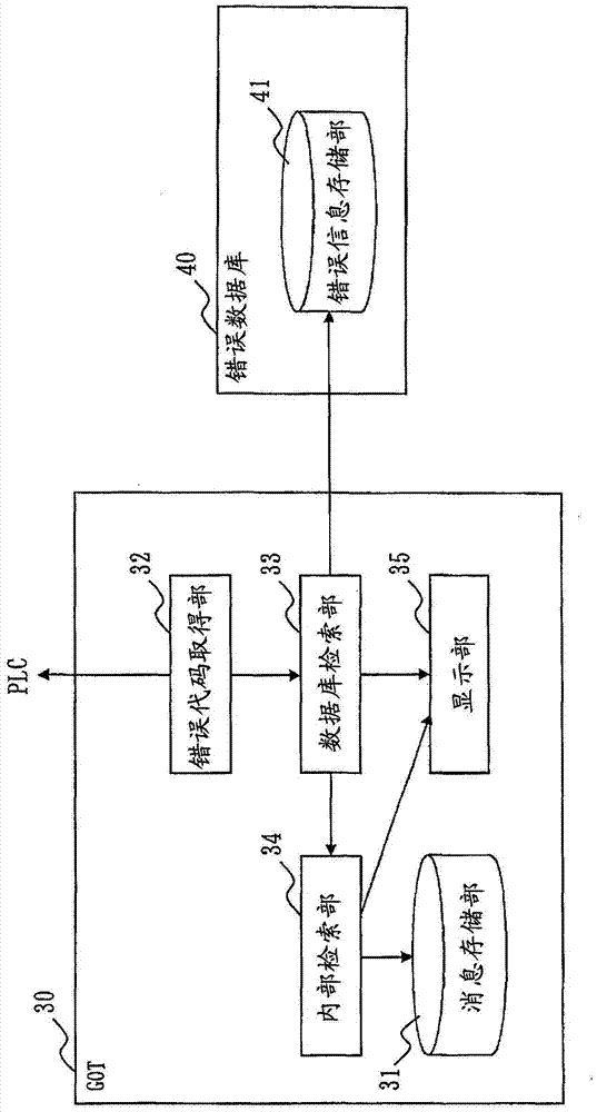
[0084] Figure 8 It is a functional configuration diagram of the GOT 30 and the error database 40 according to the second embodiment.
[0085] The functional structure of GOT30 and figure 2 The GOT30 of Embodiment 1 shown is the s...
Embodiment approach 3
[0104] In Embodiment 3, a method of automatically registering an error message will be described.
[0105] In Embodiment 3, the description will focus on parts different from Embodiment 2. FIG.
[0106] As described in Embodiment 1, the network between each GOT 30 and the error database 40 may be limited in communication traffic. Therefore, it is difficult to extract all the error codes and error messages from each GOT 30 via the network and register them in the error database 40 . However, as described in Embodiment 2, in the FA system, production products are prioritized, and it is true that workers are so busy that they hardly care about processing related to error messages. Therefore, there is a need for a structure that automatically registers necessary error messages in the error database 40 while satisfying the limitation of communication traffic.
[0107] Figure 11 It is a functional configuration diagram of the GOT 30 and the error database 40 according to the thi...
PUM
 Abstract
Description
Claims
Application Information