
Extrusion device for LED lamps
A technology of extrusion device and LED lamp, which is applied in the direction of material gluing, metal processing, connecting components, etc., can solve the problems of panel damage, panel drop, and slow installation speed, so as to enhance the aesthetic effect, speed up the installation progress, and improve safety sexual effect
- Summary
- Abstract
- Description
- Claims
- Application Information
AI Technical Summary
Problems solved by technology
Method used
Image

Examples
Embodiment Construction
[0016] Below in conjunction with accompanying drawing and embodiment the present invention will be further described:
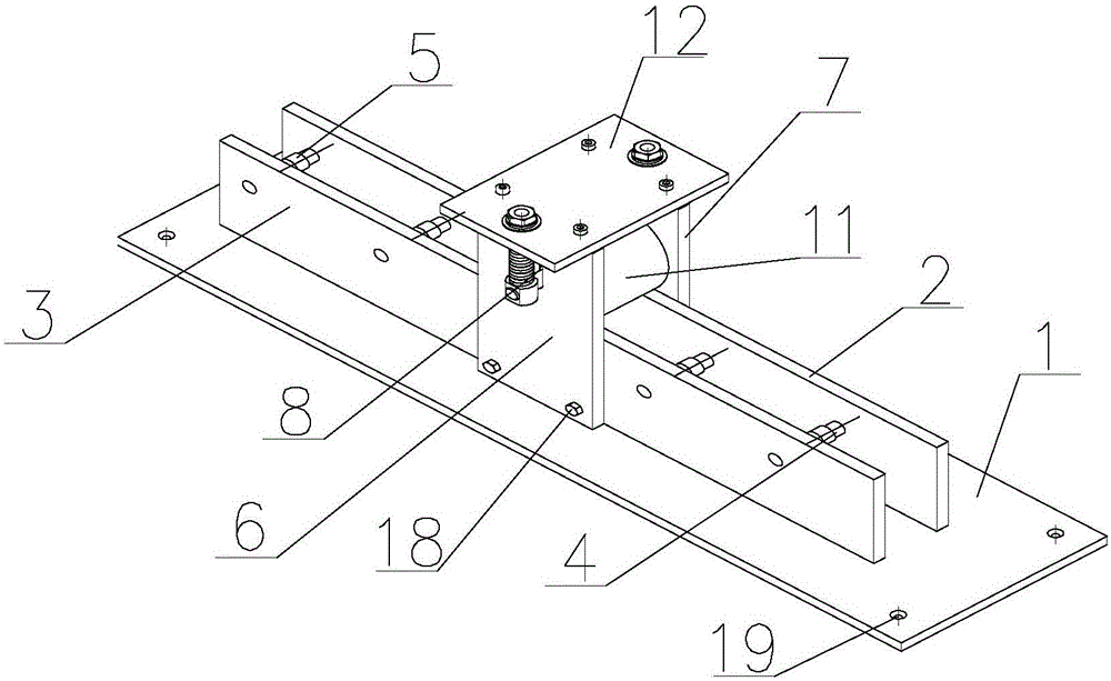
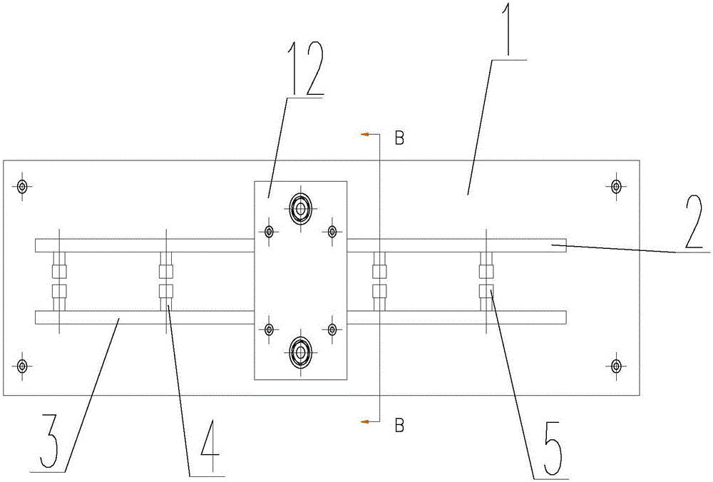
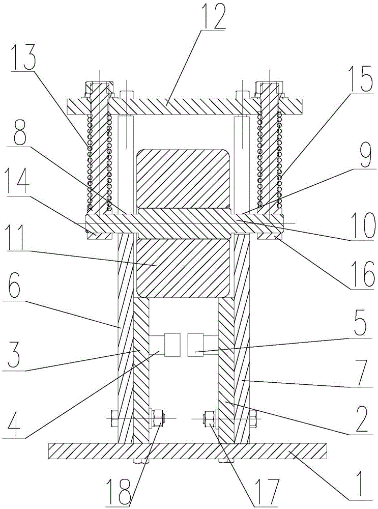
[0017] Such as Figure 1-Figure 3 As shown, an LED lamp extrusion device includes a bottom plate 1 on which several threaded holes 19 are arranged. The bottom plate 1 is provided with a first pulley mounting plate 2 and a second pulley mounting plate 3 parallel to each other, and several pulley mounting seats 4 are arranged between the first pulley mounting plate 2 and the second pulley mounting plate 3, and each pulley mounting plate 4 are respectively fixed on the first pulley mounting plate 2 and the second pulley mounting plate 3 in one-to-one correspondence, and each pulley mounting seat 4 is provided with a pulley 5 .
[0018] A first support plate 6 and a second support plate 7 are arranged on the bottom plate 1 , and the first pulley mounting plate 2 and the second pulley mounting plate 3 are located between the first support plate 6 and the second s...
PUM
 Abstract
Description
Claims
Application Information