Full-automatic film tearing machine

A fully automatic, film machine technology, applied in packaging, binding material removal, transportation and packaging, etc., can solve the problems of reducing the success rate of tearing film, clamping post film tearing mechanism, and high labor costs, so as to improve the success rate of tearing film , High film tearing success rate, high film tearing efficiency

Inactive Publication Date: 2015-12-09
SHENZHEN YONGNENG MACHINERY
View PDF8 Cites 26 Cited by
  • Summary
  • Abstract
  • Description
  • Claims
  • Application Information

AI Technical Summary

Problems solved by technology

[0003] At present, there is no equipment for tearing off the film protective film in the PCB industry. The ordinary film tearing machine can tear off the film protective film in principle, but due to the lack of adaptability, the organization has not designed for tearing the film protective film from the PCB board. The success rate of directly tearing the film is low, and the product scrap is high, so it has not been applied
Therefore, at present, the tearing work of the film protective film is still done by traditional hands, but the manual tearing efficiency is low, the labor cost is high, and the quality is difficult to guarantee.
[0004] Moreover, the tearing action of the tearing film mechanism of the existing common film tearing machine is easy to tear the film protection film, which makes it difficult to collect the torn film protection film, and after the film protection film is torn off, the film protection film is still sticky. Attached to the tearing film mechanism, resulting in confusion in the collection of the torn film protective film, and even the possibility of a post tearing film mechanism, which further reduces the success rate of tearing the film

Method used


Image

  • Full-automatic film tearing machine
  • Full-automatic film tearing machine
  • Full-automatic film tearing machine

Examples


Embodiment Construction

[0034] Below, in conjunction with accompanying drawing and specific embodiment, the present invention is described further:

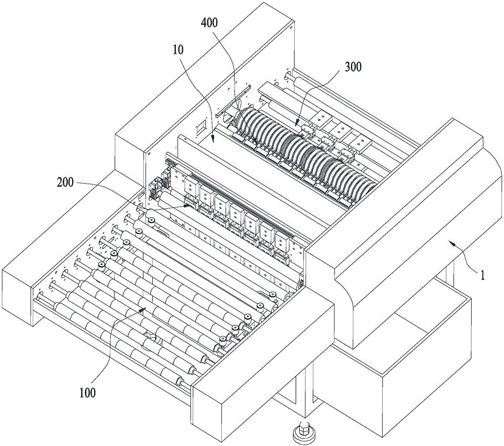
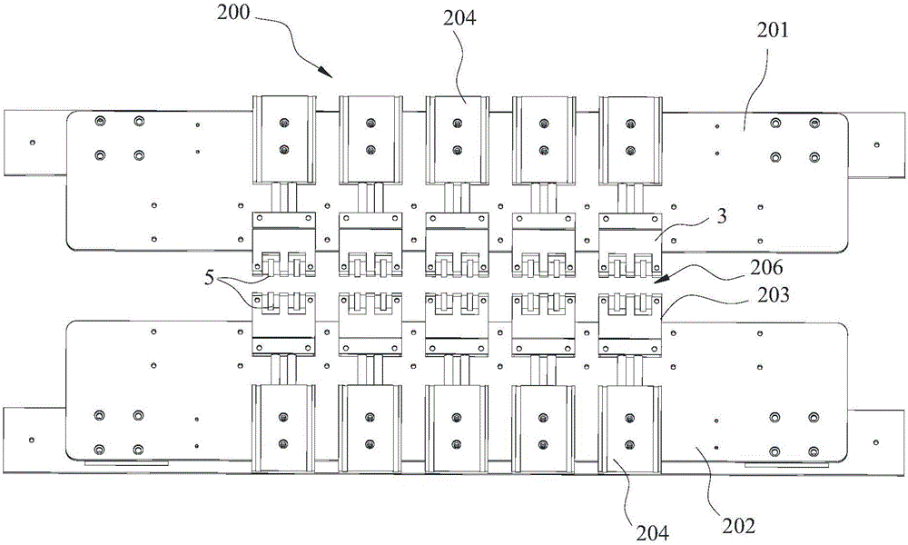
[0035] Such as figure 1 The fully automatic film tearing machine shown includes: a support 1, a conveying mechanism 100, a film lifting mechanism 200, a conductive rubber roller mechanism 300, a collecting plate 10, and a comb-shaped film separating mechanism 400, wherein: the conveying mechanism 100 is used to convey both sides A PCB board with a film protective film attached; a film-moving mechanism 200, installed on the support 1, used to stir up the edge of the film protective film, and the film-lifting mechanism 200 has a first gap 206 for the PCB board to pass through (such as figure 2 shown); the conductive rubber roller mechanism 300, which is pivotally mounted on the bracket 1, is used to adhere and wind the film protective film, and is located behind the film lifting mechanism 200 along the PCB conveying direction. The conductive rubber rolle...


PUM


Abstract

The invention discloses a full-automatic film tearing machine which comprises a support, a conveying mechanism, a film lifting mechanism, a conductive rubber covered roller mechanism, a collection board and a comb-shaped film separation mechanism. The conveying mechanism is used for conveying a PCB with film protective films bonded to the two faces; the film lifting mechanism is installed on the support, used for lifting the edges of the film protective films and provided with a first gap where the PCB penetrates; the conductive rubber covered roller mechanism is pivoted to the support, used for bonding and winding the film protective films, located behind the film lifting mechanism in the conveying direction of the PCB and provided with a second gap where the PCB penetrates; the collection board is used for stacking and collecting the film protective films and fixed to the portion, between the conductive rubber covered roller mechanism and the film lifting mechanism, of the support; and the comb-shaped film separation mechanism is installed on the collection board, used for separating the film protective films wound around the conductive rubber covered roller mechanism and located between the collection board and the conductive rubber covered roller mechanism. By the adoption of the full-automatic film tearing machine, the film protective films on the two faces of the PCB can be automatically torn away, the torn-away film protective films can be stably stacked and collected in order layer by layer, and the film tear-away success rate is increased.

Description

technical field [0001] The invention relates to a fully automatic film tearing machine. Background technique [0002] In the PCB industry, after the surface treatment of the PCB board, film protection film on the surface, and exposure, the film protection film on both sides of the PCB board needs to be torn off before entering the development and washing equipment. [0003] At present, there is no equipment for tearing off the film protective film in the PCB industry. The ordinary film tearing machine can tear off the film protective film in principle, but due to the lack of adaptability, the organization has not designed for tearing the film protective film from the PCB board. The success rate of directly tearing the film is low, and the product scrap is high, so it has not been applied. Therefore, at present, the tearing work of the film protective film is still done by traditional hands, but the manual tearing efficiency is low, the labor cost is high, and the quality is...

Claims


Application Information

Patent Timeline
Patent Type & Authority Applications(China)
IPC IPC(8): B65B69/00
CPCB65B69/0025
Inventor 张天星陆宇陈柏华肖剑文苏敏森
Owner SHENZHEN YONGNENG MACHINERY
Why Eureka
Try Eureka