
Pressing sliding door

A sliding door and threshold technology, applied in the field of doors and windows, can solve the problems of difficult to change watertight performance and airtight performance, watertight performance, poor airtight performance, shortened service life of sliding doors, etc. The effect of watertightness and airtightness

Active Publication Date: 2015-12-09
HEBEI ORIENT SUNDAR WINDOW
View PDF5 Cites 9 Cited by
  • Summary
  • Abstract
  • Description
  • Claims
  • Application Information

AI Technical Summary

Problems solved by technology

[0002] As a way of opening, sliding doors have been well known by people. Due to their own structure, compared with swing doors, sliding doors have poor watertightness and airtightness.
The main reason is that the existing sliding door installs tops in the cavity of the sliding fan, and the tops are sealed by contacting the sliding track through the tops. Under the condition of force, the tops are easily deformed, and the sealing effect cannot be achieved after deformation; frequent maintenance and replacement of tops is required. These in turn lead to shortened service life of sliding doors
Moreover, the sliding doors on the existing market are mainly aluminum alloy and plastic steel doors, and it is not easy to change their watertightness and airtightness.

Method used


Image

  • Pressing sliding door
  • Pressing sliding door
  • Pressing sliding door

Examples


Embodiment Construction

[0041] The present invention will be further described below in conjunction with the accompanying drawings and specific embodiments.

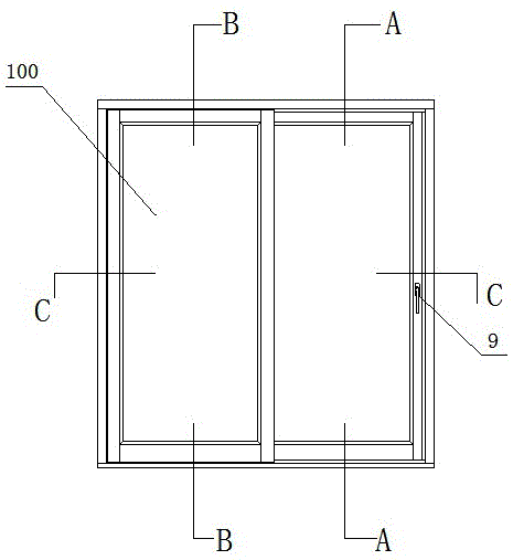
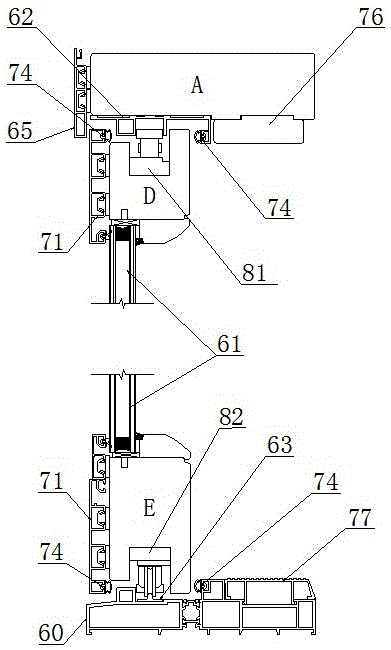
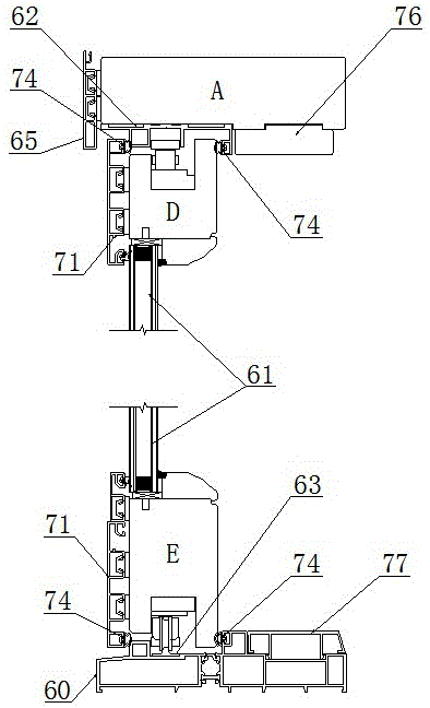
[0042] Such as figure 1 , figure 2 , image 3 , Figure 4 , Figure 5 , Image 6 , Figure 7 , Figure 8 , Figure 9 , Figure 10 , Figure 11 , Figure 12 , Figure 13 , Figure 14 , Figure 15 , Figure 16 , Figure 17 , Figure 18 , Figure 19 , Figure 20 , Figure 21 , Figure 22 with Figure 23 As shown, the present embodiment is an aluminum-clad wood press-fit sliding door, the fixed fan 100 is inside the left end room, and the push-pull fan 200 is outside the right end room. This embodiment includes a door frame consisting of an upper frame A, a threshold 60, a left frame B and a right frame C, an upper fixed sash frame F, a lower fixed sash frame G, a left fixed sash frame J, a right fixed sash frame K and glass 61 The fixed fan 100 that forms is made up of the push-pull fan 200 and the hardware system made up of...


PUM


Abstract

The invention discloses a pressing sliding door. Sealing rubber strips are fixed to the lap joint gap of a sliding sash and a fixed sash and the contact gap of the sliding sash and a door frame. An upper set of drive hardware enables two or more sash hook locks, one steering angle driver, two or more upper pulley blocks, another steering angle driver and an upper lock head to be connected in series and then fixed to a handle driver through a drive batten. A lower set of drive hardware enables two or more lower pulley blocks, a third steering angle driver and a lower lock head to be connected in series and then fixed to the handle driver through a drive batten. Rotating handles and the two sets of drive hardware move in the handle direction. An upper sliding rail, a lower sliding rail, lock hooks of the sash hook locks and the lock heads are moved indoors from the outside of a room, so that the sliding sash tightly presses the sealing rubber strips located between the sliding sash and the fixed sash, between the sliding sash and an upper frame body or a lower frame body and between the sliding sash and a right frame body or a left frame body making contact with the sliding sash, and the lock hooks of the sash hook locks tightly hook locking blocks. The pressing sliding door is good in sealing effect, water tightness and air tightness are greatly improved, locking reliability is high and the service life is long.

Description

technical field [0001] The invention belongs to the field of doors and windows, and relates to a press-fit sliding door. Background technique [0002] As a kind of opening method, sliding door has been well known by people. Compared with swing door products, sliding door has poor watertightness and airtightness due to its own structure. The main reason is that the existing sliding door installs tops in the cavity of the sliding fan, and the tops are sealed by contacting the sliding track through the tops. Under the condition of force, the tops are easily deformed, and the sealing effect cannot be achieved after deformation; frequent maintenance and replacement of tops is required. These in turn lead to a shortened service life of the sliding door. And the sliding doors on the existing market are based on aluminum alloy and plastic steel doors, which are more difficult to change its watertightness and airtightness. Contents of the invention [0003] The purpose of the pre...

Claims


Application Information

Patent Timeline
Patent Type & Authority Applications(China)
IPC IPC(8): E06B3/46E05D13/00E05B65/08E05B3/00E06B3/26E06B7/22
Inventor 倪守强宋维本耿浩
Owner HEBEI ORIENT SUNDAR WINDOW
Learn More