
connecting pin

A technology of connecting pins and pin holes, applied in the direction of bolts, etc., can solve the problems of the donkey head and the beam breaking off, the wear of the connecting pins and the pin holes, etc., and achieve the effect of reducing wear and tear.

Active Publication Date: 2017-12-05
PETROCHINA CO LTD
View PDF7 Cites 0 Cited by
  • Summary
  • Abstract
  • Description
  • Claims
  • Application Information

AI Technical Summary

Problems solved by technology

When pumping oil, the beam drives the donkey head to move up and down, and the connecting pin and pin hole are subjected to alternating loads, causing the connecting pin to move in the pin hole, resulting in wear of the connecting pin and pin hole
When the wear reaches a certain level, the strength of the connecting pin and the pin hole decreases, which may cause the donkey head to break off from the beam and cause a construction accident.

Method used


Image

  • connecting pin
  • connecting pin
  • connecting pin

Examples


Embodiment Construction

[0034] The following will clearly and completely describe the technical solutions in the embodiments of the application with reference to the drawings in the embodiments of the application. Apparently, the described embodiments are only some of the embodiments of the application, not all of them. Based on the embodiments in this application, all other embodiments obtained by persons of ordinary skill in the art without creative efforts fall within the protection scope of this application.

[0035] In the description of the present application, it should be understood that the terms "upper", "lower", "inner", "outer", etc. indicating the orientation or positional relationship are based on the orientation or position shown in the drawings of the description, and are only for convenience The description of the application and the simplified description do not indicate or imply that the device or component referred to must have a specific orientation or position, or be constructed ...


PUM


Abstract

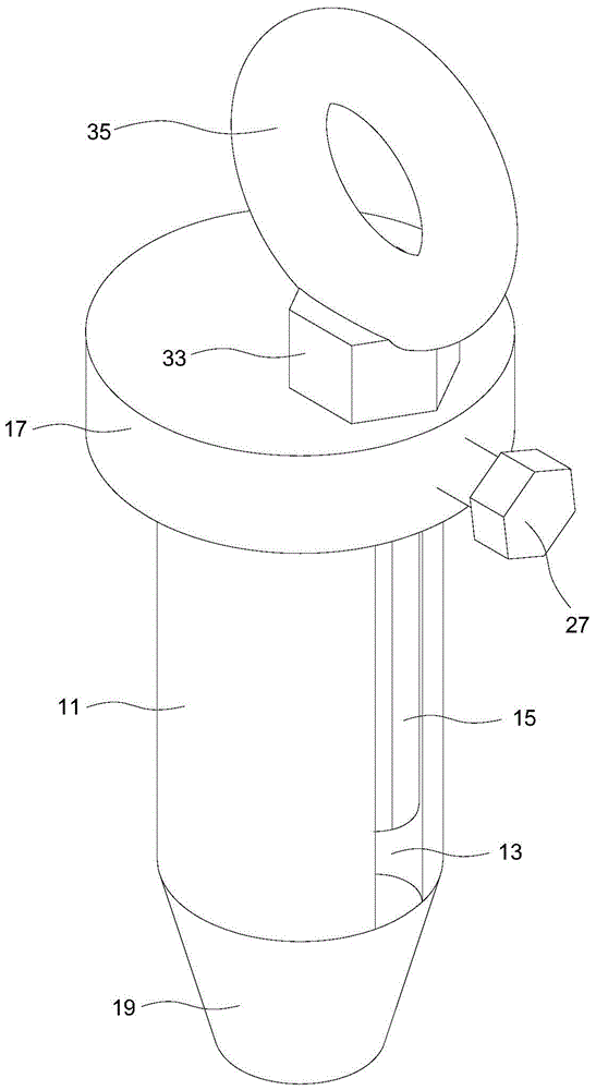
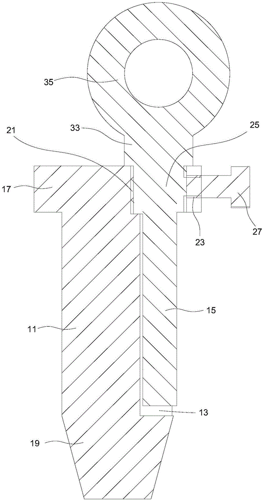
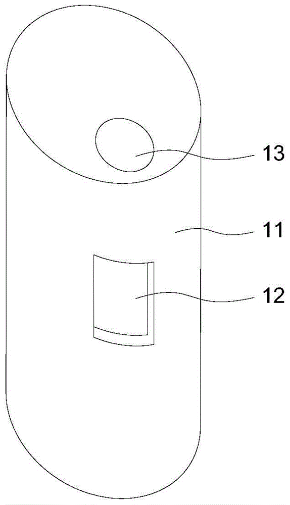
The connecting pin provided by the application can be inserted into the pin hole, and it includes: a body extending longitudinally, the body is provided with a cavity extending along the longitudinal direction, and the side wall of the body is provided with a second channel connecting the cavity and the outer space of the body A through hole; a vertically extending pole, the pole can be inserted into the cavity and rotate in the cavity, the pole has a protruding part; when the pole rotates in the cavity, the protruding part can be formed by the first A through hole exposes the inner wall of the contact pin hole. By opening a cavity on the body, inserting a pole with a protruding part into the cavity, and rotating until the protruding part exposes the first through hole and contacts the inner wall of the pin hole, the radial dimension of the body can be indirectly increased , by tightening the gap between the body and the pin hole, the gap can be reduced, so that the body and the pin hole can gradually change from a clearance fit to an interference fit, and the fastening of the connecting pin and the pin hole can be realized, and the alternating load can be slowed down. Under the action of the connecting pin, the connecting pin moves in the pin hole, reducing the wear of the connecting pin and the pin hole.

Description

technical field [0001] The present application belongs to the technical field of device connection, and in particular relates to a connection pin. Background technique [0002] In mechanical oil recovery, the beam and the donkey head of the pumping unit are usually connected by connecting pins, so that the donkey head is suspended on the beam. Specifically, a pin hole may be provided at the connection between the beam and the donkey head, and the connecting pin may be movably inserted in the pin hole to realize the detachable connection between the beam and the donkey head. [0003] Usually, in order to facilitate the insertion of the connecting pin, there is a clearance fit between the connecting pin and the pin hole. When pumping oil, the beam drives the donkey head to move up and down, and the connecting pin and pin hole are subjected to alternating loads, which makes the connecting pin move in the pin hole, resulting in wear of the connecting pin and pin hole. When the...

Claims


Application Information

Patent Timeline
Patent Type & Authority Patents(China)
IPC IPC(8): F16B19/02
Inventor 代新勇王慧聪邱衍辉李好婷胡畔朱文龙
Owner PETROCHINA CO LTD
Learn More