a lighting stand

A technology for lighting lamps and lamp holders, which is applied in the direction of lighting devices, lighting auxiliary devices, lighting and heating equipment, etc., which can solve the problems of high cost, bulky lamps, and increased volume of lamps, and achieve strong turnover, convenient use, and easy operation. simple effect

Active Publication Date: 2018-07-31
CHINA CONSTR EIGHT ENG DIV CORP LTD
View PDF11 Cites 0 Cited by
  • Summary
  • Abstract
  • Description
  • Claims
  • Application Information

AI Technical Summary

Problems solved by technology

The height adjustment devices of the existing lamps are generally cylinder lifting rods or hydraulic lifting rods. Although these height adjustment devices have high precision, they are relatively expensive, and professional manufacturers are required to provide services for maintenance, which brings a lot of inconvenience to the use.
In some occasions, although it is also necessary to adjust the height of the lamp, it does not need to be adjusted frequently. If a cylinder or hydraulic cylinder is used, the cost will be high, and the volume of the lamp will increase a lot, making the lamp very heavy.

Method used


Image

  • a lighting stand
  • a lighting stand
  • a lighting stand

Examples


Embodiment Construction

[0029] In order to make the object, technical solution and advantages of the present invention clearer, the present invention will be further described in detail below in conjunction with the accompanying drawings and embodiments. It should be understood that the specific embodiments described here are only used to explain the present invention, not to limit the present invention.

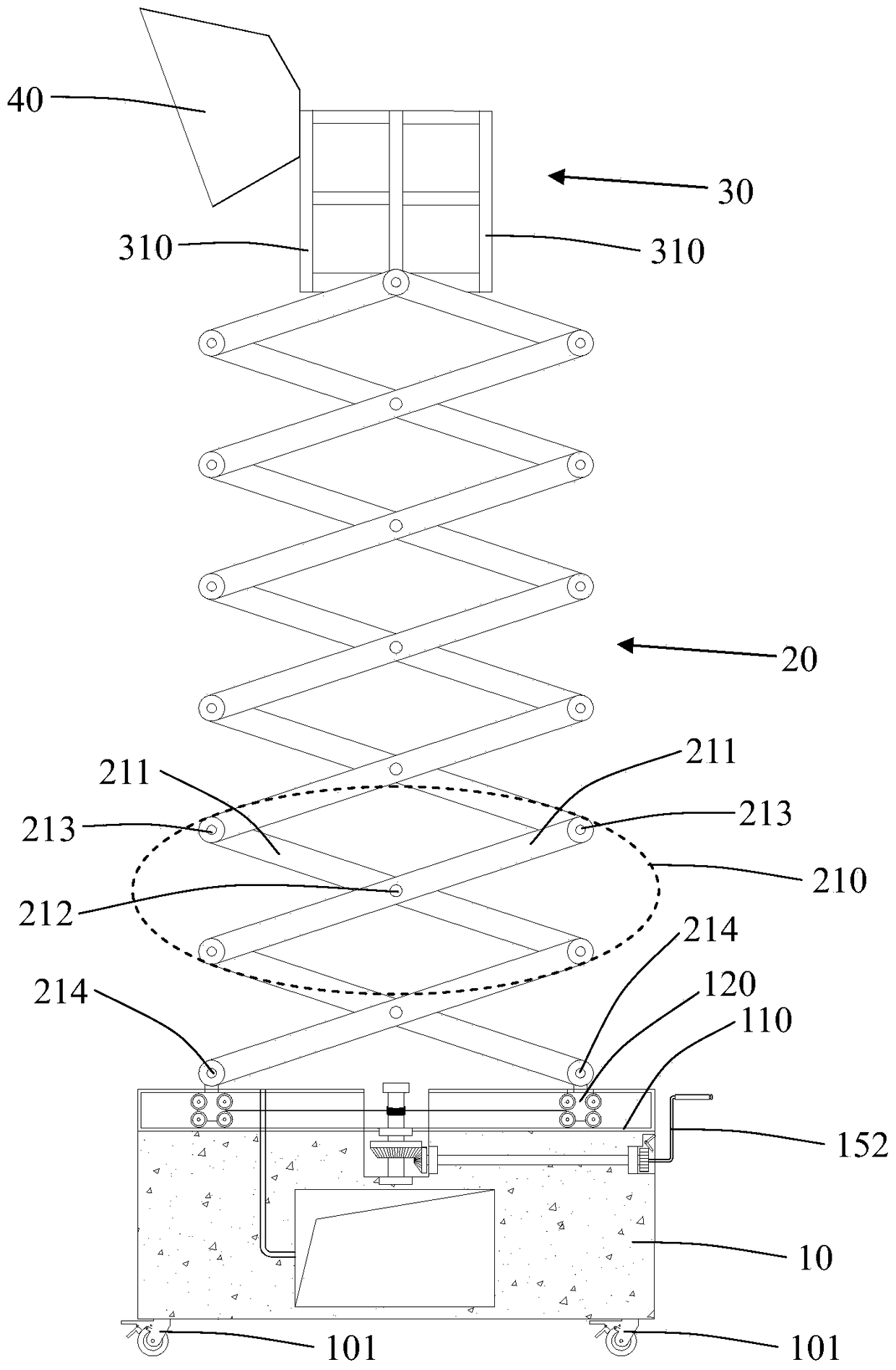
[0030] Cooperate with reference figure 1 as shown, figure 1 It is a structural schematic diagram of the lighting lamp holder of the present invention. The lighting fixture of the present invention includes:

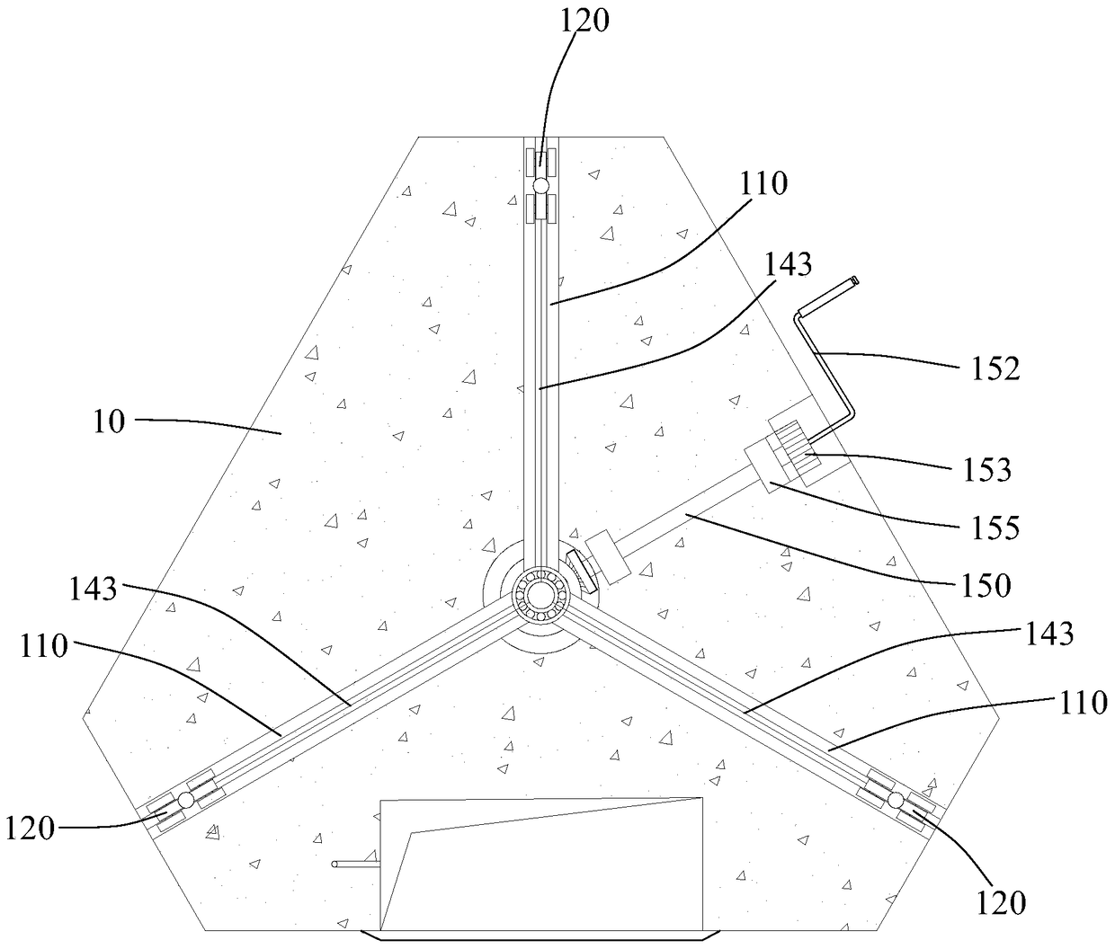
[0031] The base 10 is fixed with a chute 110 inside the chute 110, and a pulley 120 is slid in the chute 110 through a transmission mechanism, and the transmission mechanism drives the pulley 120 to move along the chute 110 in a straight line. Preferably, the bottom of the base 10 is provided with universal wheels 101 with brakes, which can realize the horizontal movement of the lighting la...


PUM


Abstract

The invention discloses a lighting lamp holder. The lighting lamp holder comprises a base, a telescopic frame, a lamp holder body and a lighting lamp. A chute is fixedly formed in the base, a pulley is arranged in the chute in a sliding mode through a transmission mechanism, and the transmission mechanism drives the pulley to linearly move along the chute. The telescopic frame is erected on the base and fixedly connected to the pulley, and the telescopic frame is driven by the pulley to ascend and descend. The lamp holder body is fixedly arranged at the top of the telescopic frame. The lighting lamp is fixedly arranged on the lamp holder body. According to the lighting lamp holder, the pulley is driven by the transmission mechanism to linearly move along the chute, the telescopic frame is further driven by the pulley to ascend and descend, and then lighting lamp holder can stretch out and contract. The lighting lamp holder is easy and convenient to assemble on a construction site, flexible to apply, easy to operate, convenient to use and high in circulation performance, resources are saved, manufacturing cost is reduced, and the requirements of green construction are met.

Description

technical field [0001] The invention relates to the technical field of building construction, in particular to an illuminating lamp stand. Background technique [0002] In building construction, there are many operations at night and in closed spaces. The existing tower cranes and fixed lighting facilities sometimes cannot meet the lighting needs of on-site construction operations, and the production and installation costs are high, which does not meet the requirements of today's green construction. [0003] In order to meet different lighting needs, the height of some lamps can be adjusted, and different lighting ranges and effects can be achieved by adjusting the height of the lamps. The height adjustment devices of the existing lamps are generally cylinder lifting rods or hydraulic lifting rods. Although these height adjustment devices have high precision, they are relatively expensive, and professional manufacturers are required to provide services for maintenance, which...

Claims


Application Information

Patent Timeline
Patent Type & Authority Patents(China)
IPC IPC(8): F21V21/22F21V23/06
CPCF21V21/22F21V23/06
Inventor 许浒雷克李晓雷张宇李金辉
Owner CHINA CONSTR EIGHT ENG DIV CORP LTD
Why Eureka
Try Eureka