Automatic detection device for dust baffle production and working method

A technology for automatic detection and dust baffles, applied in measuring devices, mechanical devices, mechanical measuring devices, etc., can solve problems such as low efficiency, reduced product qualification rate, low measurement efficiency, etc., to achieve simple operation and measurement, and improved measurement efficiency. , a wide range of effects

Active Publication Date: 2015-12-09
TAICANG SANYI HEATING & CHILLING PROJECT CO LTD
View PDF7 Cites 0 Cited by
  • Summary
  • Abstract
  • Description
  • Claims
  • Application Information

AI Technical Summary

Problems solved by technology

The motor dust shield is an important part of the motor after assembly and placed in the external environment where dust and impurities enter the motor and damage the motor. Therefore, the measurement of its size error is highly required in production. The existing measurement often uses manual comparison measurement. On the one hand The measurement efficiency is low, and multiple workers are required for assembly-line measurement. On the other hand, repetitive labor will inevitably lead to missed or false detections, which will reduce the product qualification rate (some companies increase the secondary measurement line, which will cost a lot and be inefficient). If rework It will increase the workload. If it is sold out of the factory, it will affect the reputation of the company. If it is directly transferred to the motor, there will be a major safety hazard. This is an urgent problem to be solved at present.

Method used


Image

  • Automatic detection device for dust baffle production and working method
  • Automatic detection device for dust baffle production and working method
  • Automatic detection device for dust baffle production and working method

Examples


Embodiment

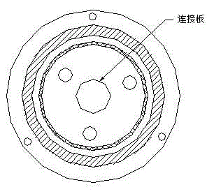
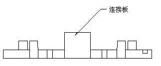
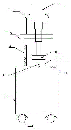
[0025] further as image 3 , Figure 4 and Figure 5 As shown, another aspect of the present invention provides a working method of an automatic detection device for dust shield production. During detection, firstly, the dust shield to be measured is inserted into the limit post 11 arranged on the dust shield fixing seat 5 Inside, the dust shield to be measured is fixed by the silk-type adjusting bolt 6 provided on the dust shield fixing seat 5, and then the control unit 14 is used to control the cylinder 7 to drive the mold base 8 with the same structure as the dust shield to be measured. Press, finally observe the scale scale 9 on the connecting part of the linkage rod 7 and the mold base 8, whether the error is within the allowable range, if so continue to the next process, if not, just select it; the control assembly 14 in this structure receives the sensor in real time The pressure information fed back by 13 controls the stroke of the cylinder 7 to prevent damage to the...


PUM


Abstract

The invention belongs to the technical field of motor accessories, and specifically discloses an automatic detection device for dust baffle production and a working method of the device. The automatic detection device includes a vertical box seat, universal wheels arranged at the bottom of the vertical box seat, an L-shaped support frame arranged at one side of the upper part of the vertical box seat, a dust baffle fixing seat arranged in the middle of the upper part of the vertical box seat and located under then L-shaped support frame, a cylinder arranged at one side of the L-shaped support frame and installed in a penetrating manner, a support arranged on the L-shaped support frame and used for installing the cylinder, a die holder connected with one end of the cylinder, a sensor arranged on the dust baffle fixing seat, and a control assembly arranged on the vertical box seat and located at one side of the dust baffle fixing seat, wherein the cylinder and the sensor are connected with the control assembly. The automatic detection device provided by the invention is reasonable in design, satisfies requirements of assembly line type measuring standards, and compared with an original measuring method, measuring efficiency is at least doubled, the die seat can be dismounted and replaced according to difference of measured products, one device with multiple purposes is realized, and the range of application is wide.

Description

technical field [0001] The invention belongs to the technical field of production and application of motor accessories, and in particular relates to an automatic detection device for dust shield production and a working method thereof. Background technique [0002] With the development of society and economy, the existing production equipment has been developing towards intelligence and automation, and various driving motors are indispensable components for mechanical equipment. Due to the different application occasions of different intelligent and automated mechanical equipment, the corresponding matching motors are also different, such as dust-proof motors, explosion-proof motors and dust-proof and explosion-proof motors. The assembly parts that make up various motors also have higher requirements, such as motor dust shields. The motor dust shield is an important part of the motor after assembly and placed in the external environment where dust and impurities enter the m...

Claims


Application Information

Patent Timeline
Patent Type & Authority Applications(China)
IPC IPC(8): G01B5/00
Inventor 林兰英
Owner TAICANG SANYI HEATING & CHILLING PROJECT CO LTD
Why Eureka
Try Eureka