
System and method for testing single noise quality in multi-source noise environment

A technology of source noise and environment, applied in the direction of measuring ultrasonic/sonic/infrasonic waves, measuring devices, instruments, etc., to achieve the effects of high test accuracy, noise control and convenient operation

Active Publication Date: 2015-12-09
BRILLIANCE AUTO
View PDF9 Cites 21 Cited by
  • Summary
  • Abstract
  • Description
  • Claims
  • Application Information

AI Technical Summary

Problems solved by technology

[0005] The purpose of the present invention is to provide a system for testing single noise quality in a multi-source noise environment, which solves many problems encountered by traditional equipment and methods in noise measurement and sound quality analysis, and has high test accuracy, easy implementation, and operation convenient

Method used


Image

  • System and method for testing single noise quality in multi-source noise environment
  • System and method for testing single noise quality in multi-source noise environment
  • System and method for testing single noise quality in multi-source noise environment

Examples


Embodiment 1

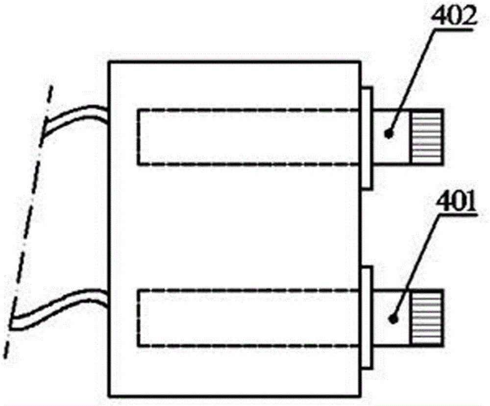
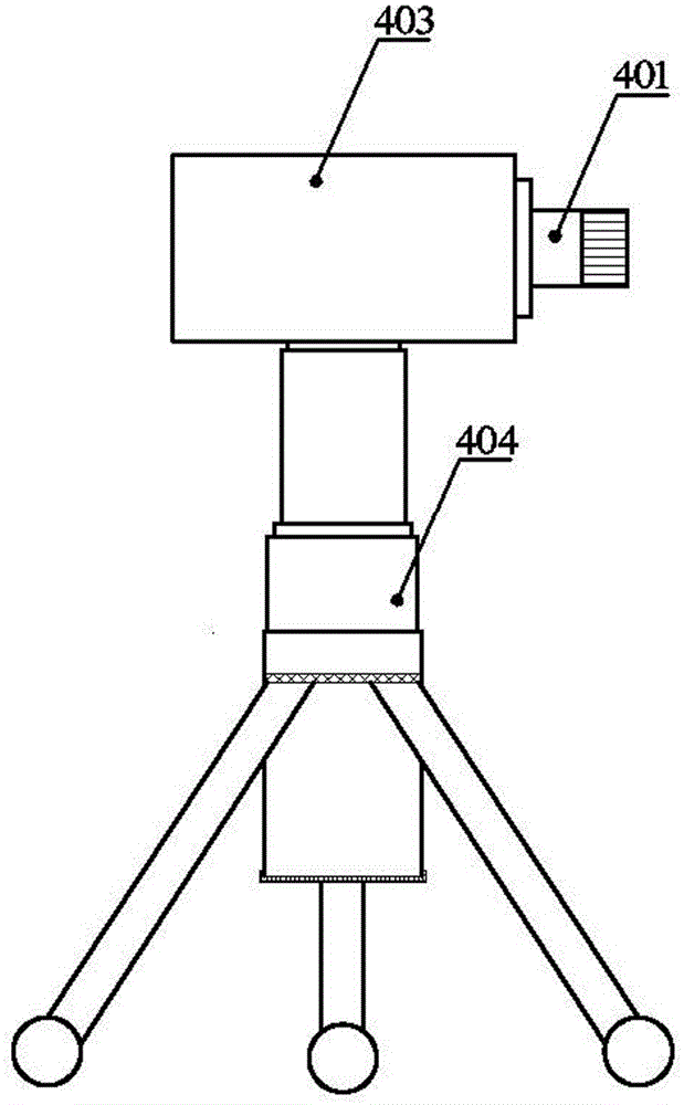
[0029] The system for testing single noise quality in the multi-source noise environment in this embodiment, such as figure 1 As shown, 1 in the figure is a computer, and 4 is a double microphone array, and this double microphone array 4 is two microphones 401 and microphone 402 arranged side by side; The output end of the analog / digital conversion board 3 is connected to the input end of the gain amplifier 3, and the output end of the gain amplifier 3 is connected to the input end of the computer 1 with a built-in signal processing module, a result output display module and a control module.

[0030] The computer 1 in this embodiment is used to control signal collection, process data and calculate sound intensity and sound quality parameters.

[0031] The gain amplifier 2 in this embodiment is used to amplify the collected signal and filter the interference signal.

[0032] The A / D conversion board 3 in this embodiment is used to convert the analog voltage signal generated b...

Embodiment 2

[0035] The difference between the system for testing single noise quality in a multi-source noise environment in this embodiment and Embodiment 1 is that the distance between the centers of the microphone 401 and the microphone 402 is 50 mm, and the corresponding test range is 30 Hz to 1200 Hz.

Embodiment 3

[0037] The difference between the system for testing a single noise quality in a multi-source noise environment in this embodiment and Embodiment 1 is that the microphone 401 and the microphone 402 are both standard 1 / 4-inch microphones, the distance between centers is 6 mm, and the corresponding test range is 6000 to 12000Hz.


PUM


Abstract

The invention provides a system and a method for testing the single noise quality in a multi-source noise environment, and relates to the field of acoustic measurement and sound quality analysis. An apparatus comprises a computer with a built-in signal processing module, a result output display module and a control module, an analog / digital conversion plate, a gain amplifier and a double-microphone array. The method includes: firstly, arranging the double-microphone array according to the position and the direction of a noise source; acquiring signals, calculating the sound intensity, and performing noise separation; and calculating the loudness and sharpness according to the sound intensity, and performing sound quality evaluation. According to the method, sound quality parameters are employed to evaluate the acoustic characteristics of a specific component in the mixed noise, the method is in accordance with the ear acoustic characteristic, the test is more targeted, and the noises can be more effectively controlled. According to the system, the realization is easy, the operation is convenient, the test precision is high, the blanks in the fields of acoustic tests and sound quality analysis are filled in, and the system can be widely applied to noise control engineering in multiple fields such as automobiles, spaceflight, and household electrical appliances etc.

Description

technical field [0001] The invention relates to the technical fields of acoustic measurement, psychoacoustic analysis and sound quality evaluation, in particular to a multi-source noise environment that separates a specific noise component and measures and analyzes its sound quality in a multi-source noise environment. A system for testing a single noise quality. Background technique [0002] With the development of science and technology and the improvement of living standards, people's requirements for noise are becoming more and more stringent. Effective noise control methods and means need to be formulated according to the specific noise generation mechanism, transmission path, frequency characteristics and auditory characteristics of the human ear, which requires accurate measurement and evaluation of noise. At present, the measurement of noise generally uses the sound pressure level as the evaluation standard. The defect of this method is that the sound pressure level...

Claims


Application Information

Patent Timeline
Patent Type & Authority Applications(China)
IPC IPC(8): G01H11/08
Inventor 徐勇王晖赵珩王洋
Owner BRILLIANCE AUTO
Learn More