
A pulse waveform modulation circuit

A circuit and modulation signal technology, applied in the field of pulse waveform modulation circuit, can solve the problems of inconvenient modification, high cost and high cost, and achieve the effect of simple implementation method and low hardware cost

Active Publication Date: 2017-12-01
河南辉瑞生物医电技术有限公司
View PDF5 Cites 0 Cited by
  • Summary
  • Abstract
  • Description
  • Claims
  • Application Information

AI Technical Summary

Problems solved by technology

The process of ISD circuit production and implementation, first, the sound needs to be edited through an external sound production tool to complete a sound segment that meets industry standards, and then the sound is played through the speaker and the sound is collected and transcribed to the storage part of the ISD chip through the microphone. The sound clip to be played. Finally, input the playback command and record the playback time for playback. Not only the production and modification time is long, but also the cost is high
The DAC circuit production and implementation process is similar, but the storage location is in the control unit, and the whole picture of the entire sound needs to be simulated to meet the standard requirements. Because it describes the full waveform, there is a large amount of DAC waveform data that needs to be stored and takes up a lot of control units. In short, the cost is high and the modification is inconvenient

Method used


Image

  • A pulse waveform modulation circuit
  • A pulse waveform modulation circuit
  • A pulse waveform modulation circuit

Examples


Embodiment Construction

[0012] In conjunction with the accompanying drawings, the present invention is further described in detail through the embodiments.

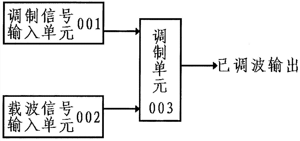
[0013] Such as figure 1 combine figure 2 As shown: the medical device alarm circuit of the modulated waveform described in this embodiment includes an input modulation signal unit 001, an input carrier signal unit 002 and a modulation unit 003, and the modulation unit 003 is connected to the input modulation signal unit 001 and the input carrier signal unit respectively 002 connection. The input modulation waveform ( figure 2 As shown) the input modulation signal is input to one end of the modulator through the follower composed of the input modulation signal unit 001; the input carrier waveform ( image 3 As shown) the switching circuit composed of the input carrier signal unit 002 performs chopping modulation on the input modulation signal unit 001, and the modulation unit 003 performs modulation and multiplication operations on the input...


PUM


Abstract

A pulse waveform modulation circuit disclosed by the present invention includes a modulation signal input unit (001), a carrier signal input unit (002) and a modulation unit (003), and the modulation signal input unit and carrier signal input unit are modulated by the modulation unit Modulation of the modulation signal input unit. The present invention aims at the current use of dedicated audio dedicated chips and other solutions. Although they can meet the standard requirements, they basically have the disadvantages of relatively high hardware costs, inconvenient modification, and the need for special burning and programming. While meeting the requirements of the existing industry standards for medical alarm sounds, it can also make the output audio signal contain more harmonic waveforms, making it softer, more delicate and durable, and more in line with the auditory characteristics of the human ear, making the hardware cost of the circuit low and the implementation method Simple, can quickly meet the requirements of the standard.

Description

technical field [0001] The invention relates to a pulse waveform modulation circuit. Background technique [0002] At present, in the industry standard of the medical device alarm system, there are detailed requirements on the medical conditions that trigger the sound alarm to the frequency and waveform of the sound alarm. Clinically, when an alarm occurs on a medical alarm instrument, medical staff expect to be able to deduce the urgency, severity, and even level of the alarm from the sound alarm, so as to take corresponding measures to deal with it. However, the standard also requires that the sound should be non-intrusive and non-startling, and that its sound pressure level should under no circumstances exceed that of a medium-priority signal. At present, special audio dedicated chips and other solutions are used. Although they can meet the standard requirements, they basically have high hardware costs, inconvenient modification, and special programming is required. For...

Claims


Application Information

Patent Timeline
Patent Type & Authority Patents(China)
IPC IPC(8): G08B3/10
Inventor 王勇崔婷婷葛苒陈川川
Owner 河南辉瑞生物医电技术有限公司
Learn More