Laser confocal LIBS, Raman spectrum-mass spectrum imaging method and Raman spectrum-mass spectrum imaging device

A technology of Raman spectroscopy and mass spectrometry imaging, which is applied in the directions of measuring devices, Raman scattering, and material excitation analysis, etc. It can solve the problems of low spatial resolution, drift, and large laser focus spot of mass spectrometry detection, and improve spatial resolution. , compress the size, and suppress the effect of drifting

Inactive Publication Date: 2015-12-09
BEIJING INSTITUTE OF TECHNOLOGYGY
View PDF5 Cites 21 Cited by
  • Summary
  • Abstract
  • Description
  • Claims
  • Application Information

AI Technical Summary

Problems solved by technology

[0005] 1) Due to the use of simple laser focusing to desorb and ionize the sample, there are still problems such as large laser focusing spot and low spatial resolution of mass spectrometry detection;
[0006] 2) It is impossible to detect neutral atoms, molecules, neutral ions and gr...

Method used


Image

  • Laser confocal LIBS, Raman spectrum-mass spectrum imaging method and Raman spectrum-mass spectrum imaging device
  • Laser confocal LIBS, Raman spectrum-mass spectrum imaging method and Raman spectrum-mass spectrum imaging device
  • Laser confocal LIBS, Raman spectrum-mass spectrum imaging method and Raman spectrum-mass spectrum imaging device

Examples


Embodiment 1

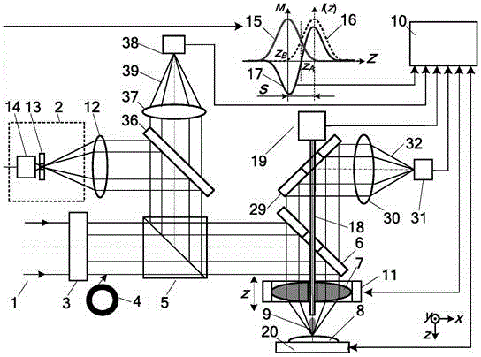
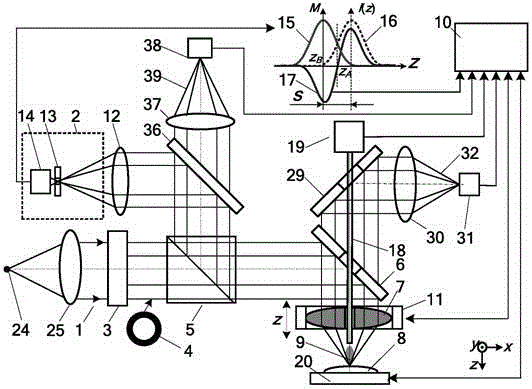
[0052] The embodiments of the present invention are based on Figure 4 The shown high spatial resolution laser confocal spectroscopy-mass spectroscopy microscopic imaging device includes a laser point light source system 24, a collimator lens 25 placed along the optical axis, an outgoing beam attenuator 34, a ring light generating system 3, and a beam splitter 5 The mesoporous dichroic 6 and the mesoporous measurement objective lens 7 which is located in the refraction direction of the optical axis and focuses the mesoporous dichroic device 6 to reflect the light beam to the tested sample 8, including the reflected light intensity of the focused spot for detecting the mesoporous measurement objective 7 The signal is a confocal light intensity detection system composed of a detection beam attenuator 35, a dichroic beam splitter 36, a collecting lens 12, and a light intensity point detector 2 located at the focal point of the laser lens 12, which is used to detect the center hole m...

Embodiment 2

[0075] Such as Figure 4 As shown, in the laser confocal LIBS, Raman spectroscopy, and mass spectrometry imaging device of Embodiment 1, the computer 10 can follow the position z corresponding to the maximum value M of the confocal axial intensity curve 15 B Value to control the axial objective lens scanner 11 to focus the focal spot of the mesoporous measurement objective lens 7 on the sample 8 to be measured.

Embodiment 3

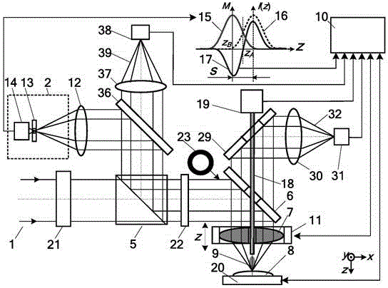
[0077] Such as Figure 5 As shown, in the laser confocal LIBS, Raman spectroscopy and mass spectrometry imaging device of Embodiment 1, the ring light generating system 3 is replaced by a vector beam generating system 21 and a pupil filter 22 that are placed along the optical axis to generate a vector beam. A ring beam 23 is generated, and the ring beam is reflected by the mesopore dichroic 6 and the mesopore measurement objective lens 7 is focused into a tiny spot exceeding the diffraction limit to illuminate the sample 8 to be tested.

[0078] The rest of the imaging measurement method is the same as in Example 1.


PUM


Abstract

The invention relates to a laser confocal LIBS, a Raman spectrum-mass spectrum imaging method and a Raman spectrum-mass spectrum imaging device and belongs to the technical fields of confocal microscopy imaging, mass spectrum imaging and spectral measurement. In the invention, the confocal microscopy imaging technology is combined with a spectrum and mass spectrum detection technology; a high-spatial-discrimination confocal system is used for axially focusing and imaging a sample; a mass spectrum detection system is used for performing mass spectrum detection to charged molecules and atoms in a sample microcell; and a spectral detection system is used for performing microcell spectrum detection to focal spot excitation spectrums (Raman spectrum and induced breakdown spectrum) of a confocal microscopy system, thereby achieving high-spatial discrimination and high-sensitivity imaging and detection of complete component information and configuration parameters of the sample microcell. The invention achieves advantage complement and structure and function fusion of laser poly-spectrum component imaging detection (mass spectrum, Raman spectrum and laser-induced breakdown spectrum). The method and the device have wide application prospect in the fields of biology, physical chemistry, micro-fabrication and nano-fabrication and the like.

Description

Technical field [0001] The invention belongs to the fields of confocal microscopy imaging technology, spectral imaging technology and mass spectrometry imaging technology. It combines laser confocal microscopy imaging technology, laser induced breakdown spectral imaging technology, Raman spectral imaging technology and mass spectrometry imaging technology, and relates to a high spatial resolution Laser confocal induced breakdown, Raman spectroscopy-mass spectrometry microscopic imaging methods and devices have broad application prospects in the fields of biology, materials, minerals, and micro-nano manufacturing. technical background [0002] Mass Spectrometry (MassSpectrometry) ionizes the components in the sample, so that the generated charged atoms, molecules or molecular fragments with different charge-to-mass ratios are separately focused under the action of electric and magnetic fields to obtain a spectrum arranged in order of the mass-to-charge ratio. instrument. Mass spe...

Claims


Application Information

Patent Timeline
IPC IPC(8): G01N21/17G01N21/65G01N21/63
Inventor 邱丽荣赵维谦王允
Owner BEIJING INSTITUTE OF TECHNOLOGYGY
Why Eureka
Try Eureka