High spatial resolution laser dual-axis differential confocal mass spectrometry imaging method and device
A two-axis differential confocal and high spatial resolution technology, which is applied in the field of confocal microscopy imaging and mass spectrometry imaging, can solve the problems of low spatial resolution of mass spectrometry detection, long mass spectrometry imaging time, and large laser focus spot, etc. Spatial resolution, overcoming the interference of stray light on the focal plane, and strong anti-stray light ability
- Summary
- Abstract
- Description
- Claims
- Application Information
AI Technical Summary
Problems solved by technology
Method used
Image
Examples
Embodiment 1
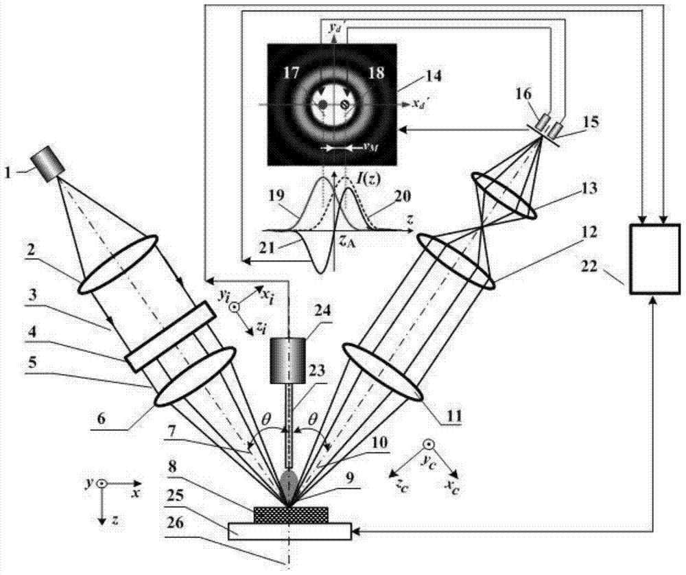
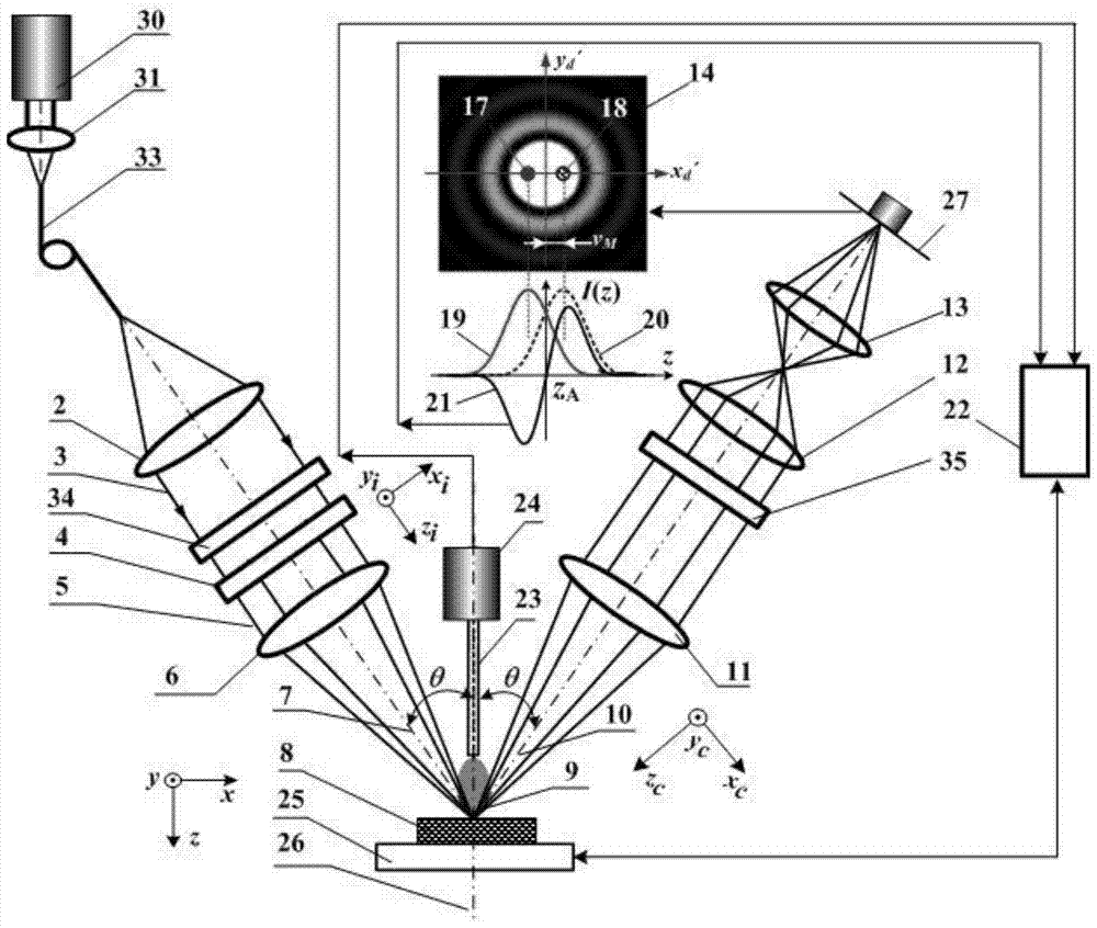
[0040] The embodiment of the present invention is based on image 3 The shown high spatial resolution laser dual-axis differential confocal mass spectrometry microscopic imaging device uses a pulsed laser 30, a condensing lens 31 and a light-transmitting optical fiber 33 at the focus of the condensing lens to replace figure 1In the point light source 1, a CCD detector 27 is used to replace the first light intensity point detector 15 and the second light intensity point detector 16 located on the focal plane of the relay magnifying lens 13 and placed symmetrically with respect to the collection optical axis 10 . exist image 3 The exit beam attenuator 34 is introduced into the laser focusing system of the laser, and the detection beam attenuator 35 is introduced into the laser dual-axis differential confocal detection system.
[0041] Such as image 3 As shown, the high spatial resolution laser dual-axis differential confocal mass spectrometer imaging device includes a pulsed...
Embodiment 2
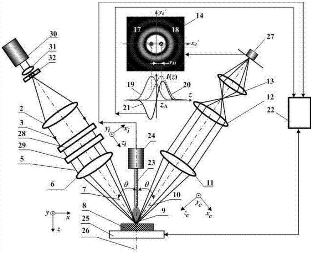
[0061] Such as figure 2 In the shown high spatial resolution laser dual-axis differential confocal mass spectrometer imaging device, the point light source 1 consists of a pulsed laser 30 along the direction of the incident optical axis 7, a condenser lens 31, and a pinhole 32 at the focal point of the condenser lens 31. Instead, the ring light generating system 4 can be replaced by a vector beam generating system 28 and a pupil filter 29, and the first light intensity point detector 15 and the second light intensity point detector 16 located at the focal plane of the relay magnifying lens 13 are controlled by a CCD Detector 27 instead.
[0062] The radially polarized light longitudinal field tight focusing system composed of the vector beam generating system 28, the pupil filter 29 and the measuring objective lens 6 is used to compress the lateral size of the focused spot.
[0063] The remaining imaging measurement methods are the same as in Example 1.
PUM
 Abstract
Description
Claims
Application Information
 - R&D
- Intellectual Property
- Life Sciences
- Materials
- Tech Scout
- Unparalleled Data Quality
- Higher Quality Content
- 60% Fewer Hallucinations
Browse by: Latest US Patents, China's latest patents, Technical Efficacy Thesaurus, Application Domain, Technology Topic, Popular Technical Reports.
© 2025 PatSnap. All rights reserved.Legal|Privacy policy|Modern Slavery Act Transparency Statement|Sitemap|About US| Contact US: help@patsnap.com


