
Power supply circuit

A technology of power supply circuit and switching power supply circuit, which is applied in the direction of adjusting electric variables, control/regulation systems, instruments, etc., and can solve the problems of easily burnt circuit, mismatch between pressure cooker and power box, and different volume of power box

Inactive Publication Date: 2015-12-09
杜培植
View PDF7 Cites 1 Cited by
  • Summary
  • Abstract
  • Description
  • Claims
  • Application Information

AI Technical Summary

Problems solved by technology

[0002] Existing power circuits used in pressure cookers, pressure cookers or rice cookers of different power need to apply power circuits of different specifications, and the volumes of power circuits of different specifications are different, resulting in different sizes of power boxes, and the inside of the pressure cooker is used to install the power box. At the same time, pressure cookers with different power need to install power boxes of different specifications. When installing the power box, it is easy to install the wrong one, so that the pressure cooker does not match the power box, and it is easy to burn out the circuit when the pressure cooker is working.

Method used


Image

  • Power supply circuit
  • Power supply circuit

Examples


Embodiment Construction

[0015] A further detailed description will be made below in conjunction with the accompanying drawings and embodiments of the present invention:

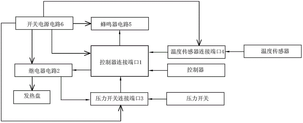
[0016] Such as figure 1 As shown, a power supply circuit includes a controller connection port 1 and a heating plate, the controller connection port 1 is connected with a relay circuit 2 for controlling whether the heating plate is energized, a pressure switch connection port 3, a temperature sensor connection port 4, A buzzer circuit 5 and a switching power supply circuit 6 , the switching power supply circuit 6 is connected to the relay circuit 2 , the pressure switch connection port 3 , the temperature sensor connection port 4 and the buzzer circuit 5 .

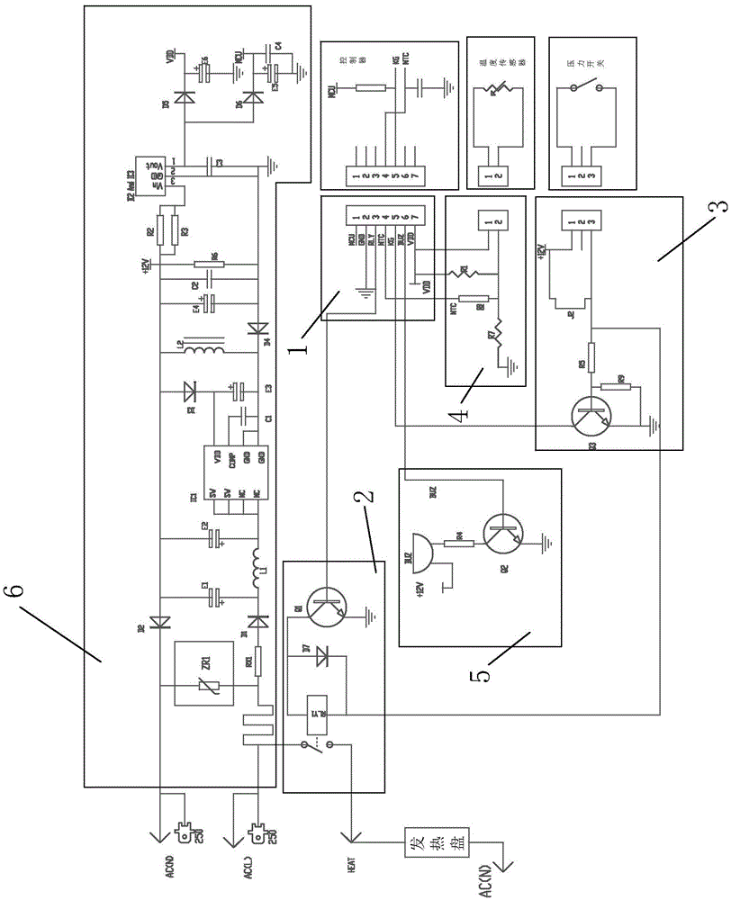
[0017] The relay circuit 2 includes a relay RLY1, a diode D7 and a triode Q1. One end of the coil of the relay RLY1 is respectively connected to the positive terminal of the diode D7 and the collector of the triode Q1. The negative terminal of the diode D7 is connected to the ot...


PUM


Abstract

The invention discloses a power supply circuit comprising a controller connecting port and a heating plate; the controller connecting port is connected with a relay circuit used for controlling the heating plate to be powered up or not, a pressure switch connecting port, a temperature sensor connecting port, a buzzer circuit, and a switch power supply circuit; the power supply circuit is respectively connected with the realty circuit, the pressure switch connecting port, the temperature sensor connecting port, and the buzzer circuit via circuits; the pressure cooker and electric rice cooker dual-purpose power supply circuit allows the pressure cookers of different power to use the same power supply circuit.

Description

[technical field] [0001] The invention relates to a power circuit. [Background technique] [0002] Existing power circuits used in pressure cookers, pressure cookers or rice cookers of different power need to apply power circuits of different specifications, and the volumes of power circuits of different specifications are different, resulting in different sizes of power boxes, and the inside of the pressure cooker is used to install the power box. At the same time, pressure cookers with different powers need to install power boxes of different specifications. When installing the power box, it is easy to install the wrong one, so that the pressure cooker does not match the power box, and it is easy to burn out the circuit when the pressure cooker is working. [Content of the invention] [0003] The present invention overcomes the disadvantages of the above technologies, and provides a power circuit, a dual-purpose power circuit for a pressure cooker and an electric rice coo...

Claims


Application Information

Patent Timeline
IPC IPC(8): G05F1/14
Inventor 杜培植
Owner 杜培植
Features
  • Generate Ideas
  • Intellectual Property
  • Life Sciences
  • Materials
  • Tech Scout
  • Unparalleled Data Quality
  • Higher Quality Content
  • 60% Fewer Hallucinations
Learn More