Induction cooking heater

a technology of induction heating and cooker, which is applied in the direction of electric/magnetic/electromagnetic heating, deep-fat fryers, cooking vessels, etc., can solve the problems of preventing the temperature of the load pan from being detected precisely and quickly, and achieve the effect of preventing unintended heating from continuing

Active Publication Date: 2006-04-20
PANASONIC CORP
View PDF1 Cites 81 Cited by
  • Summary
  • Abstract
  • Description
  • Claims
  • Application Information

AI Technical Summary

Benefits of technology

[0006] This induction heating cooker detects a temperature change of the load pan accurately by detecting an infrared radiation from the load pan, and detects the temperature of the load pan by the heat conduction from the pan even if ambient light enters, thereby preventing unintended heating from continuing.

Problems solved by technology

Therefore, in the former case that a thermo-sensitive element, such as a thermistor, receives heat by heat conduction, a delay of a thermal response of the top place causes a large temperature difference between the temperature detected by the thermO-sensitive element and an actual temperature of the load pan, thus preventing the temperature of the load pan from being detected precisely and quickly.

Method used


Image

  • Induction cooking heater
  • Induction cooking heater
  • Induction cooking heater

Examples


exemplary embodiment 1

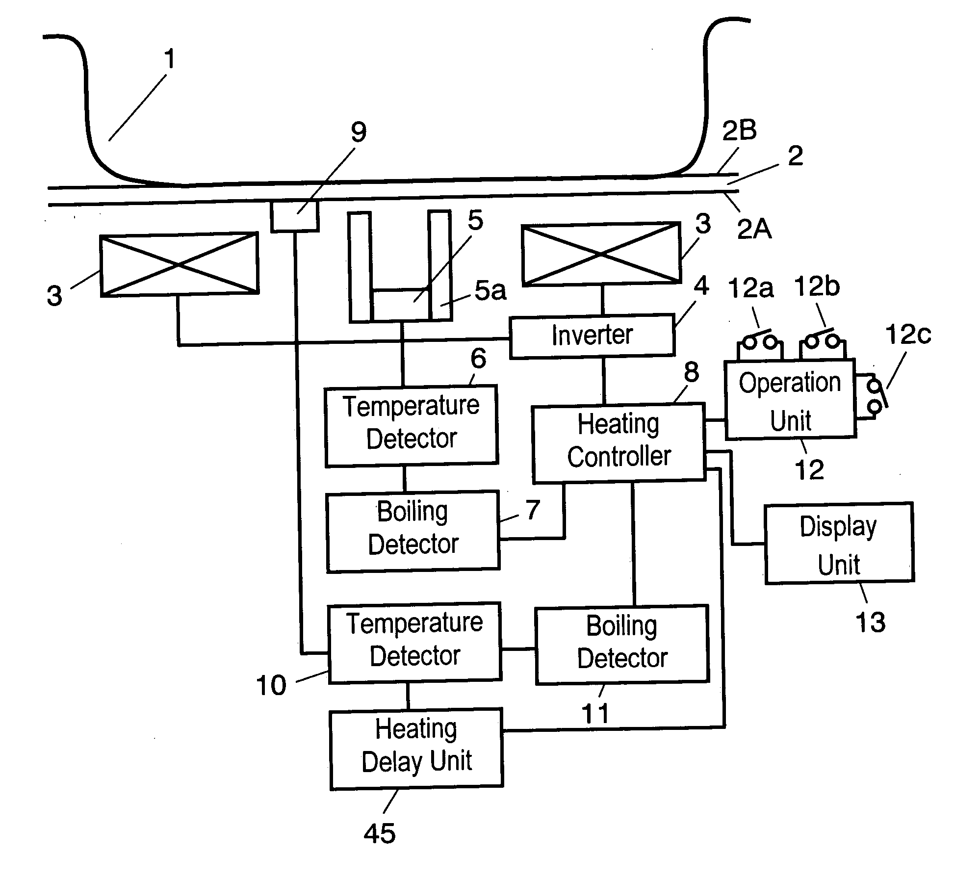
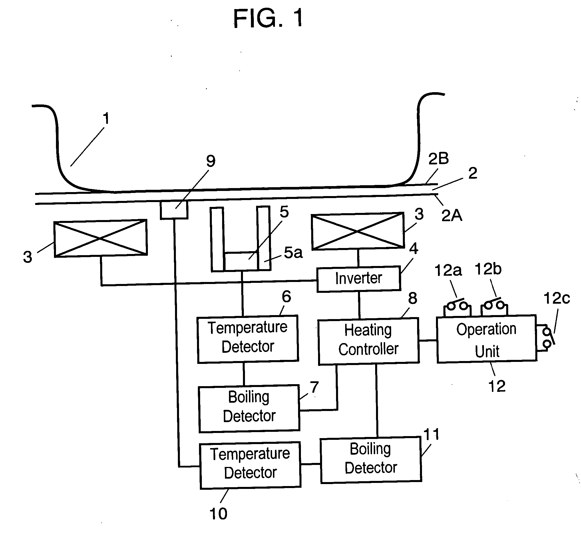
[0016]FIG. 1 is a block diagram of an induction heating cooker according to Exemplary Embodiment 1 of the present invention. Pan 1, a load pan accommodating water therein, is placed on top surface 2B, a first surface, of top plate 2 made of ceramic that is transparent and infrared-transmittable. Heating coil 3 accommodated in a case under bottom surface 2A, a second surface, of top plate 2 inductionally-heats pan 1. Heating coil 3 is a single annular heating coil having an opening in its center. In FIG. 1, heating coil 3 is shown as two separate parts and a cross section of its wound wired portion is shown schematically. Inverter 4 supplies a high-frequency current to heating coil 3. Infrared detector 5 detects the amount of infrared radiation having a predetermined frequency range and outputs a current corresponding to the amount. Infrared detector 5 is located at the center of heating coil 3 and under heating coil 3, and is surrounded by reflective cylinder 5a having an opening to...

exemplary embodiment 2

[0030]FIG. 3 is a block diagram of an induction heating cooker according to exemplary Embodiment 2 of the present invention. The induction heating cooker of Embodiment 2 includes boiling detector 111 which operates differently from boiling detector 11 shown in FIGS. 1 and 2. Other components are identical to those of the induction heating cooker of Embodiment 1, and their description will be omitted.

[0031]FIG. 4 is a flowchart illustrating an operation of the induction heating cooker of Embodiment 2. An operation of boiling detector 111 will be particularly described. When a water boiling instruction is input through switch 12b, heating coil 3 heats pan 1 for 60 seconds at a predetermined heating output (Step 21). Then, boiling detector 111 stores temperature T1 of bottom surface 2A of top plate 2 detected by temperature detector 10 (Step 22). Heating coil 3 heats pan 1 for another 60 seconds with the predetermined heating output (Step 23), that is, heats pan 1 for 120 seconds in t...

exemplary embodiment 3

[0033]FIG. 5 is a block diagram of an induction heating cooker according to exemplary Embodiment 3 of the present invention. Only differences from the induction heating cooker of Embodiment 1 shown in FIG. 1 will be described.

[0034] Thermistor 41, as a thermo-sensitive element contacts bottom surface 2A of top plate 2 so as to receive the heat from bottom surface 2A at the upper part of heating coil 3 by heat conduction. Temperature detector 42 measures the temperature of bottom surface 2A and converts the temperature into temperature data. Thermistor 41 is located above heating coil 3 and closer to the periphery of heating coil 3 than thermistor 9. In other words, thermistor 41 is located at a position exposing to a more magnetic field generated by heating coil 3 than thermistor 9. Boiling detector 43 detects the boiling of water in pan 1 according to the sequence shown in FIG. 2 or 4 based on the temperature data output from temperature detector 42.

[0035] When either boiling det...


PUM


Abstract

An induction heating cooker includes a surface, a heating coil for inductionally-heating a load pan, an inverter for supplying a high-frequency current to the heating coil, an infrared detector which detects infrared radiation emitted from the load pan and is located under a top plate, a first temperature detector for detecting a temperature of the load pan based on an output of the infrared detector, a heating controller for controlling a power output from the inverter, a thermo-sensitive element for receiving heat from the top plate, and a second temperature detector for detecting a temperature of the load pan based on an output of the first thermo-sensitive element. This induction heating cooker detects a temperature change of the load pan accurately by detecting an infrared radiation from the load pan, and detects the temperature of the load pan by the heat conduction from the pan even if ambient light enters.

Description

TECHNICAL FIELD [0001] The present invention relates to an induction heating cooker for heating a load pan with its output controlled based on the temperature of the load pan. BACKGROUND ART [0002] In a conventional induction heating cooker disclosed in Japanese Patent Laid-Open Publication No. 2003-317919 for heating a load pan, a thermistor contacting a bottom surface of a top plate on which the load pan placed measures the temperature of the load pan. [0003] In another conventional induction heater disclosed in Japanese Patent Laid-Open Publication No. 2003-317918 for heating a load pan, an infrared sensor mounted detects infrared radiation emitted from the load pan through an infrared-transmitting portion provided in a top plate, and measures the temperature of the load pan without contacting. [0004] The top plate used in induction heating cooker is generally made of ceramic and has a low thermal conductivity. Therefore, in the former case that a thermo-sensitive element, such a...

Claims


Application Information

Patent Timeline
Patent Type & Authority Applications(United States)
IPC IPC(8): H05B1/02H05B6/12A47J27/00H05B6/06
CPCH05B6/062H05B2213/07
Inventor NIIYAMA, KOJIISHIMARU, NAOAKIHAJI, MASAYOINUI, HIROFUMI
Owner PANASONIC CORP
Why Eureka
Try Eureka