
Position sensor

A sensor and part technology, applied in instruments, light guides, optics, etc., can solve the problem of inability to detect accurate pressing positions, and achieve the effect of improving detection accuracy

Inactive Publication Date: 2015-12-09
NITTO DENKO CORP
View PDF6 Cites 0 Cited by
  • Summary
  • Abstract
  • Description
  • Claims
  • Application Information

AI Technical Summary

Problems solved by technology

That is, at this time, since the light-receiving element detects the light from the outside (external disturbance light) in addition to the light from the light-emitting element, the external disturbance light becomes noise, making it impossible to detect an accurate signal. pressing position

Method used


Image

  • Position sensor
  • Position sensor
  • Position sensor

Examples


Embodiment

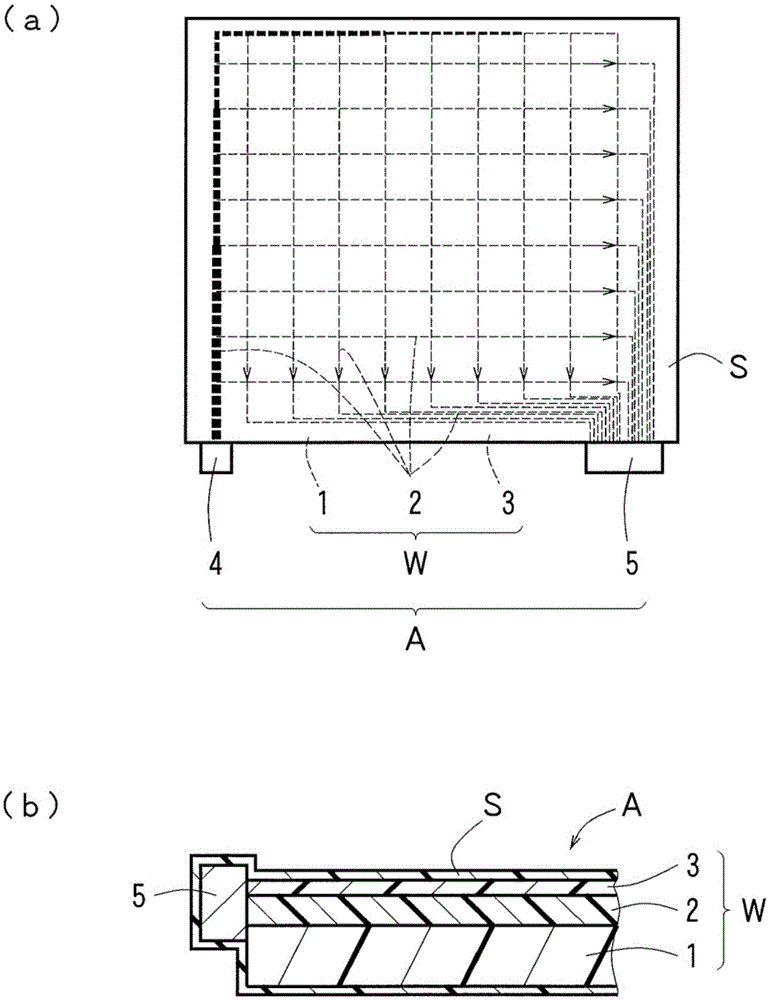
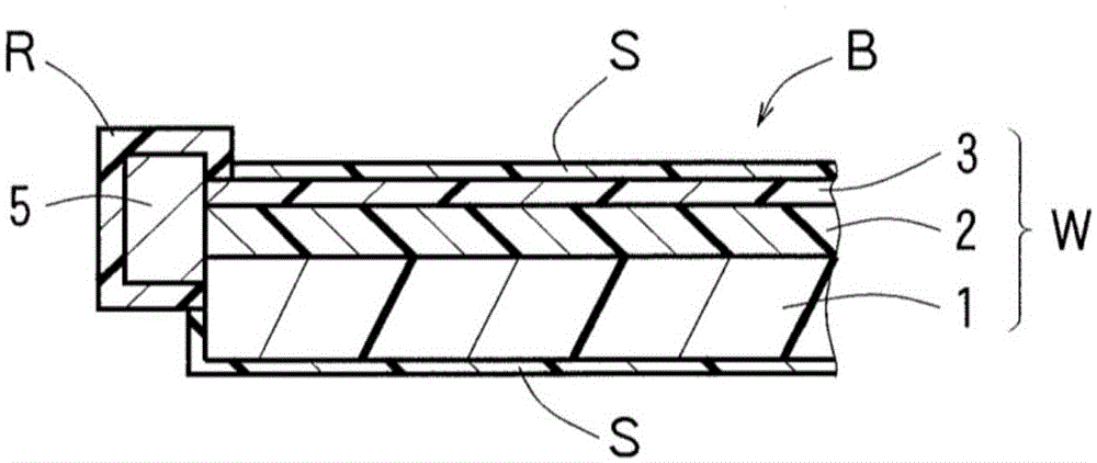
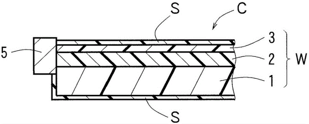
[0041] As a position sensor, a device whose entirety is covered with a light-shielding layer is prepared (refer to figure 1 (a), (b)). That is, the upper surface of the upper cladding layer of the position sensor is coated with a light-shielding sheet (75 μm in thickness) by means of a double-sided adhesive tape (25 μm in thickness), and the lower surface of the lower cladding layer is covered by a light-shielding sheet (75 μm in thickness) by means of a double-sided adhesive tape (50 μm in thickness). A light-shielding plate (thickness 1 mm) is covered, and the outer surface of the light-emitting element and the outer surface of the light-receiving element are covered by a light-absorbing resin layer. In addition, the end face of the core, the light-emitting element, and the light-receiving element are bonded using ultraviolet curable resin. The forming materials and the like of each structure are as follows.

[0042] (light shielding layer and double-sided tape)

[0043]...


PUM


Abstract

The present invention provides a position sensor in which a light-receiving element is disabled from detecting light from the outside. This position sensor (A) is provided with: a sheet-like optical waveguide (W) in which a plurality of linear cores (2) are arranged and formed in a lattice shape on the surface of a sheet-like under-clad layer (1), and an over-clad layer (3) is formed in a sheet shape while covering these cores; a light-emitting element (4) connected to one end face of the cores (2); and a light-receiving element (5) connected to the other end face of the cores (2). The whole area of the outer surface of the optical waveguide (W) and the whole area of the outer surface of the light-receiving element (5) are covered by a light-shielding sheet (S) for shielding light in wavelengths recognized by the light-receiving element.

Description

technical field [0001] The invention relates to a position sensor for optical detection of a pressed position. Background technique [0002] Conventionally, a position sensor that optically detects a pressed position has been proposed (for example, refer to Patent Document 1). In this position sensor, a plurality of cores serving as optical paths are arranged vertically and horizontally, and the peripheries of these cores are covered with a clad to form a sheet, and light from a light emitting element is incident on one end surface of each of the cores, and The light transmitted through the inside of each core is detected by a light receiving element at the other end surface of each core. Then, when a part of the surface of the sheet-like position sensor is pressed with a finger or the like, the core of the pressed part is crushed (the cross-sectional area of ​​the core decreases in the pressing direction), and at the core of the pressed part, light is transmitted. As the ...

Claims


Application Information

Patent Timeline
Patent Type & Authority Applications(China)
IPC IPC(8): G06F3/042G02B6/12G02B6/122
CPCG02B6/125G06F3/0421G06F2203/04107
Inventor 吉冈良真清水裕介
Owner NITTO DENKO CORP
Learn More