A glue injection device

A glue injection device and glue injection technology, applied in the glue injection field, can solve the problems of glue drop, glue backflow, waste of resources, etc., and achieve the effects of easy disassembly, increased resistance, and simple coordination

Active Publication Date:
View PDF6 Cites 0 Cited by
  • Summary
  • Abstract
  • Description
  • Claims
  • Application Information

AI Technical Summary

Problems solved by technology

The current glue injection devices all have a glue injection head. The inventors found that after the glue injection head in the prior art stops injecting glue, a certain amount of glue will continue to drip, resulting in waste of resources.
In addition, the current injection head can be equipped with a stirring device, and the driving mechanism that drives the stirring device to rotate is generally installed outside the injection head, and needs to be inserted into the injection head through a rotating shaft to drive the stirring device to rotate. The inventors found that, The glue in the mixing chamber will flow to other positions of the injection head or out of the injection head through the gap between the rotating shaft and the wall of the through hole of the rotating shaft, resulting in backflow of the glue during injection, etc.

Method used


Image

  • A glue injection device
  • A glue injection device
  • A glue injection device

Examples


Embodiment Construction

[0030] Those skilled in the art will be more aware of the above and other objects, advantages and features of the present invention according to the following detailed description of specific embodiments of the present invention in conjunction with the accompanying drawings.

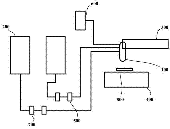
[0031] figure 1 is a schematic schematic diagram of a glue injection device according to an embodiment of the present invention. Such as figure 1 As shown, the glue injection device may include at least one glue tank 200, at least one pumping device 500, a glue injection head 100, a moving mechanism 300, a working platform 400 and a control device. Each glue tank 200 is used to hold glue liquid. The glue injection head 100 is installed on the moving mechanism 300 to move according to a preset track driven by the movement mechanism 300 . The glue injection head 100 is provided with at least one glue inlet hole 51 , and a glue injection channel is defined in the glue injection head 100 . Each pumping de...


PUM


Abstract

The invention provides a glue injection device, which includes a moving mechanism, a working platform and a control device, wherein it also includes: at least one glue tank; a glue injection head installed on the movement mechanism, and at least one glue inlet is provided on the glue injection head holes and pressure holes, and the glue injection head is defined with a glue injection channel; at least one pumping device, each pumping device is configured to transport the glue in a glue tank to the glue tank through a glue inlet hole under the control of the control device The glue injection channel is used to inject glue to the object placed on the working platform; and the pressure device is connected to the pressure hole and is configured to: when the glue injection is stopped or a preset time after the glue injection is stopped, it is controlled by the control device Open it down to make the upper end of the glue injection channel form a negative pressure; or, when cleaning the glue injection head, open it under the control of the control device to make the upper end of the glue injection channel form a positive pressure. The glue injection device can prevent the glue liquid from continuing to drop after the glue injection is stopped, and can prevent the backflow of the glue liquid in the glue injection head during glue injection.

Description

technical field [0001] The invention relates to the technical field of glue injection, in particular to a glue injection device. Background technique [0002] The glue injection device is an automatic machine that controls the fluid, and drips, coats, and pots the liquid on the surface of the product or inside the product, so that it can achieve the functions of sealing, fixing, and waterproofing. Generally, two sets of equipment are used. part glue. It is mainly used for bonding, pouring, coating, sealing and filling of glue, oil and other liquids in the product process. The automatic glue injection device can realize the glue filling of irregular graphics such as points, lines, arcs and circles. The current glue injection devices all have a glue injection head, and the inventors have found that a certain amount of glue will continue to drip after the glue injection head in the prior art stops injecting glue, resulting in waste of resources. In addition, the current glue ...

Claims


Application Information

Patent Timeline
Patent Type & Authority Patents(China)
IPC IPC(8): B05C5/02B05C11/10B05B15/02
Inventor 邓波鹿敏
Why Eureka
Try Eureka