Wiring method for main line rail and return cable of new subway traction power supply line system

A main line rail and return cable technology, applied in power lines, power rails, transportation and packaging, etc., can solve the problems of increasing hidden trouble spots, unreasonable connection schemes between return cables and rails, and adding intermediate conversion links, etc. The effect of promoting application value, improving security and stability, and reducing maintenance costs

Active Publication Date: 2018-05-15
CHINA RAILWAY ELECTRIFICATION SURVEY DESIGN & RES INST
View PDF4 Cites 0 Cited by
  • Summary
  • Abstract
  • Description
  • Claims
  • Application Information

AI Technical Summary

Problems solved by technology

[0006] (2) Half of the return cables are not directly led to the return box, but the current path of this part is rail → return cable → rail → return cable → return box, which increases the intermediate conversion link and increases the number of potential failure points
[0007] 3. The reason for the above problems is that the connection scheme between the return cable and the rail is unreasonable, and half of the return cable is transferred back to the return box through the rail

Method used


Image

  • Wiring method for main line rail and return cable of new subway traction power supply line system
  • Wiring method for main line rail and return cable of new subway traction power supply line system
  • Wiring method for main line rail and return cable of new subway traction power supply line system

Examples


Embodiment 1

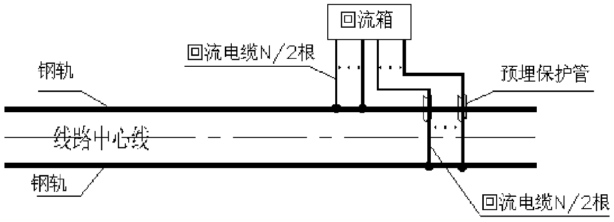
[0029] Such as image 3 In the connection and wiring method between the return cable and the rail (1), the connection method between the main line rail and the return cable of the new subway traction power supply line system, the specific steps are as follows:

[0030] (1) Lead out N flexible cables from the reflow box;

[0031] (2) Weld N / 2 flexible cables drawn from the reflow box directly to the adjacent rail;

[0032] (3) Weld the remaining N / 2 flexible cables drawn out to another rail through the embedded protective tube on the ballast bed;

[0033] The pre-embedded protective pipe in the above method is arranged inside the ballast bed, which avoids the damage of cables during rail construction and maintenance;

[0034] The material of the embedded protection pipe is glass steel pipe or galvanized steel pipe;

[0035] The diameter of the embedded protective tube is >1.3 times the diameter of the cable, which is determined according to the specific project.

Embodiment 2

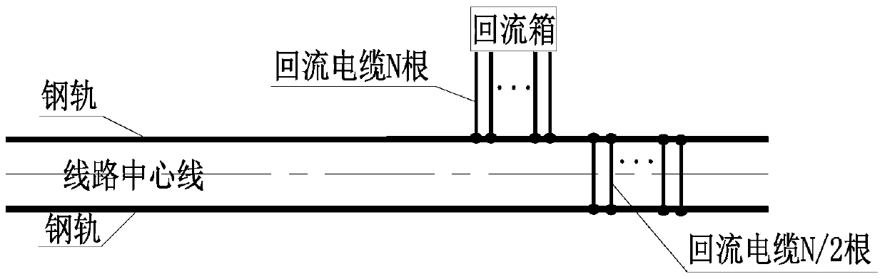
[0037] Such as Figure 5 In the connection and wiring method (2) between the return cable and the rail shown, the specific steps for the connection method between the main line rail and the return cable of the new subway traction power supply line system are as follows:

[0038] (1) Lead out N flexible cables from the reflow box;

[0039] (2) Take the N / 2 flexible cables drawn from the return box, place N / 2 flexible cables in the embedded protection tube, and lead them out to the side of the rail near the center line of the line through the lower part of the ballast bed welding;

[0040] (3) Weld the remaining N / 2 flexible cables drawn out to another rail through the embedded protective tube on the ballast bed;

[0041] The pre-embedded protective pipe in the above method is arranged inside the ballast bed, which avoids the damage of cables during rail construction and maintenance;

[0042] The material of the embedded protection pipe is glass steel pipe or galvanized steel...


PUM


Abstract

The present invention relates to the field of wiring methods for subway traction power supply systems, in particular to a new type of method for connecting main line rails of subway traction power supply line systems and return cables. The specific methods are as follows: (1) lead out N flexible cables from the return box; ) Weld the N / 2 flexible cables drawn from the reflow box to the adjacent rail; (3) Weld the remaining N / 2 flexible cables drawn out to another steel rail through the embedded protective tube on the ballast bed superior. The present invention overcomes the disadvantages of using rails for conversion through different wiring methods and pre-embedded cable protection tubes, the connection point between rails and cables is reduced by 50%, and at the same time overcomes the problems caused by cables and cable connections in the prior art. The influence of the resistance difference between the rails improves the safety and stability of the subway circuit system.

Description

technical field [0001] The invention relates to the field of wiring methods for a subway traction power supply system, in particular to a novel method for wiring a main line rail and a return cable of a subway traction power supply system. Background technique [0002] At present, in the subway traction power supply system, the rail return mode is generally adopted. The typical diagram of the subway traction power supply system is as follows: figure 1 shown. The current path is: positive pole of traction substation → feeder line → catenary → vehicle (load) → rail → return line → negative pole of traction substation. Among them, the connection between the rail and the return line is one of the important links to ensure the reliable operation of the traction power supply system. At the same time, in order to minimize the impact of the return cable connection on the rail, the connection points between the cable and the rail should be minimized. [0003] 1. Current technical ...

Claims


Application Information

Patent Timeline
Patent Type & Authority Patents(China)
IPC IPC(8): B60M1/00B60M1/30
Inventor 赵海军王立天丁为民王胜李金华白雪莲皋金龙田胜利朱晓军吴云飞李晶王正
Owner CHINA RAILWAY ELECTRIFICATION SURVEY DESIGN & RES INST
Why Eureka
Try Eureka