
Electromagnetic pressure protection water discharge valve

An electromagnetic, drainage valve technology, applied in the valve details, valve device, valve shell structure and other directions, can solve the problems of small drainage diameter, insufficient flow, water accumulation in the compartment, etc., to avoid water leakage and air leakage, and take up less space. , the effect of fewer connection points

Active Publication Date: 2011-06-15
深圳市垅运照明电器有限公司
View PDF6 Cites 3 Cited by
  • Summary
  • Abstract
  • Description
  • Claims
  • Application Information

AI Technical Summary

Problems solved by technology

[0003] However, due to the vastness of the north and south of China and the large climate difference, after a period of use, the mechanical pressure protection drain valve has poor environmental adaptability and is not suitable for installation outside the compartment; too many connection points and curvature are difficult to fix, not only The volume is large, the drainage diameter is small, the flow rate is not enough, the ability to resist foreign objects is poor, and it is easy to block. Moreover, the rubber tube connected at the connection point is also poor in adaptability to the vibration of the train, and it is prone to water and air leakage; Floor drains cannot be installed, which can easily lead to water accumulation inside the compartment
[0004] Therefore, the existing technology still needs to be improved and developed

Method used


Image

  • Electromagnetic pressure protection water discharge valve
  • Electromagnetic pressure protection water discharge valve
  • Electromagnetic pressure protection water discharge valve

Examples


Embodiment Construction

[0027] The specific embodiments and examples of the present invention will be described in detail below in conjunction with the accompanying drawings. The described specific embodiments are only used to explain the present invention, and are not intended to limit the specific embodiments of the present invention.

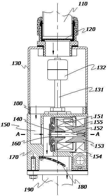
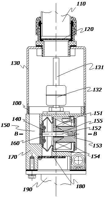
[0028] The electromagnetic pressure protection drain valve of the present invention includes a valve body 100 and a valve 140, one of its specific implementations is as figure 1 As shown, it can be connected between the drainage inlet 110 and the drainage outlet 190, for example, in the wash room of the train carriage, installed at the bottom of the sink, etc.; the valve body 100 is provided with a drainage channel 150, and the valve 140 is in the drainage channel 150 It can be set movable; wherein, a solenoid valve is also arranged on the valve body 100, and the valve 140 is installed on the solenoid valve; the valve is opened and closed by the action of the armatur...


PUM


Abstract

The invention discloses an electromagnetic pressure protection water discharge valve. The valve is connected between a water discharge inlet and a water discharge outlet, and comprises a valve body and a valve, wherein a water discharge passage is formed in the valve body; the valve is movably arranged in the water discharge passage; the valve body is provided with an electromagnetic valve; and the valve is arranged on the electromagnetic valve and is opened and closed through the action of an armature of the electromagnetic valve. Due to the adoption of the electromagnetic valve, the water discharge valve is opened and closed through the action of the electromagnetic valve, so that water is not required to be discharged by squeezing by using the gravity of the water to prevent the phenomenon of water logging due to incapable discharge of a small amount of water when the water is available, and the valve is not required to be sealed through air pressure to overcome the defect of difficulty in sealing of the valve in the presence of insufficient air pressure when the water is not available, and the valve is not influenced by vibration produced during running of a train to prevent water leakage and air leakage phenomena caused by the vibration; and the valve fills the blank in the technology of the pressure protection water discharge valve of a domestic high speed train of China and has great practical value for the domestication of the China high-speed multiple units.

Description

technical field [0001] The invention relates to the field of pressure protection drain valves, and more specifically, the improvement relates to electromagnetic pressure protection drain valves. Background technique [0002] Nowadays, high-speed EMUs, that is, high-speed trains, have entered an era of rapid development. The mechanical pressure protection drain valves used in the sewage discharge facilities on China’s high-speed train carriages are all imported; the mechanical pressure protection drain valves use the gravity of water to squeeze the sewage out; when there is no water, they are The valve is sealed by air pressure. [0003] However, due to the vastness of the north and south of China and the large climate difference, after a period of use, the mechanical pressure protection drain valve has poor environmental adaptability and is not suitable for installation outside the compartment; too many connection points and curvature are difficult to fix, not only The vol...

Claims


Application Information

Patent Timeline
Patent Type & Authority Applications(China)
IPC IPC(8): F16K31/06F16K27/00F16K49/00
Inventor 何世群孙帮成熊剑春刘雄
Owner 深圳市垅运照明电器有限公司
Learn More