Lifting-force-reinforced wing section based on Magnus principle

An airfoil and lift technology, which is applied in the fields of aerospace and ship engineering, can solve the problems that cannot be solved, such as the increase of airfoil resistance, and achieve the effects of enhancing lift, reducing eddy current, and facilitating installation

Active Publication Date: 2015-12-16
JIANGSU UNIV OF SCI & TECH
View PDF3 Cites 2 Cited by
  • Summary
  • Abstract
  • Description
  • Claims
  • Application Information

AI Technical Summary

Problems solved by technology

This phenomenon has been partially used, but through the inspection of multiple airfoil patents and existing airfoil objects, it is found that when the airfoil is working, the drag of the airfoil is caused by the f

Method used


Image

  • Lifting-force-reinforced wing section based on Magnus principle
  • Lifting-force-reinforced wing section based on Magnus principle

Examples


Embodiment Construction

[0017] The present invention will be further described below in conjunction with drawings and embodiments.

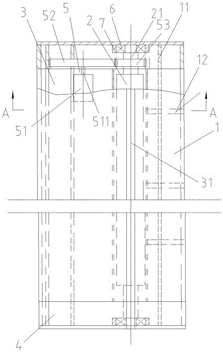
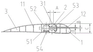
[0018] Such as figure 1 and figure 2 As shown, the present invention includes a front wing body 1, a Magnus cylinder 2 and a tail wing body 3, and the longitudinal ends of the front wing body 1 and the tail wing body 3 are vertically fixedly connected to the sealing body 4 respectively A lift-enhancing airfoil with a streamlined cross-section, a Magnus cylinder 2 is embedded between the front wing body 1 and the rear wing body 3, and the front wing body 1 and the rear wing body 3 The part adjacent to the Magnus cylinder 2 is concaved into an arc shape matching the Magnus cylinder 2 . Both the front wing body 1 and the tail wing body 3 are closed shells, and several rows of longitudinal ribs with different heights are respectively arranged at intervals in the shell of the front wing body 1 and in the shell of the tail wing body 3 plate 11 to improve the structural s...


PUM


Abstract

The invention discloses a lifting-force-reinforced wing section based on the Magnus principle. The lifting-force-reinforced wing section comprises a front wing body, a Magnus cylinder and a tail wing body; the longitudinal ends of the front wing body and the longitudinal ends of the tail wing body are respectively, vertically and fixedly connected with opening sealing bodies to form the lifting-force-reinforced wing section with the cross section in a streamline shape; the Magnus cylinder is embedded between the front wing body and the tail wing body, and a driving device of the Magnus cylinder is arranged in one opening sealing body and the tail wing body; and a plurality of air inlet pipe horizontally penetrating through the front wing body are longitudinally arranged in the front wing body at intervals. The Magnus cylinder is embedded between the front wing body and the tail wing body, so that wing wake flow is improved, and tail vortex is reduced. Furthermore, the Magnus cylinder is convenient to install, disassemble and replace. The air inlet pipes on the upper side of the central line of the Magnus cylinder can supplement the air volume to guarantee that the Magnus cylinder can generate pressure difference. Thus, the lifting force can be further reinforced.

Description

technical field [0001] The invention relates to a device for increasing the lift of an airfoil, in particular to a device for increasing the lift of an airfoil by using the Magnus effect, and belongs to the technical fields of aerospace and ship engineering. Background technique [0002] The airfoil structure is widely used in aircraft and ship engineering. When sailing at high speed, the aircraft or hydrofoil can provide lift through the airfoil to lift the aircraft off the ground or lift the hydrofoil out of the water to reduce navigational resistance. [0003] The Magnus principle refers to a phenomenon in which a rotating cylinder moving in a viscous incompressible fluid is subjected to a lifting force. This phenomenon has been partially used, but through the inspection of multiple airfoil patents and existing airfoil objects, it is found that when the airfoil is working, the drag of the airfoil is caused by the forward movement of the Magnus roller that provides lift. ...

Claims


Application Information

Patent Timeline
IPC IPC(8): B64C3/00B64C23/08
Inventor 张胜杨松林王涛申继鹏
Owner JIANGSU UNIV OF SCI & TECH
Why Eureka
Try Eureka