
Low noise axial fan with rotary deflecting ring

A technology of axial flow fan and guide ring, which is applied in the field of train air conditioner condenser, low noise axial flow fan and axial flow fan, which can solve the problems of noise pollution, high impeller speed and high sound pressure level, and improve the suction flow field , reduce the import resistance, increase the effect of added work

Inactive Publication Date: 2006-06-28
SHANGHAI JIAO TONG UNIV
View PDF0 Cites 12 Cited by
  • Summary
  • Abstract
  • Description
  • Claims
  • Application Information

AI Technical Summary

Problems solved by technology

The train air-conditioning device for urban rail transit requires compact size and low noise, but the inlet of the fan in service is in the shape of a sudden contraction, and there is a serious disadvantage of eddy current at the suction end. Therefore, a higher technology is proposed for the axial flow fan used in the air-conditioning condenser Require
[0003] The most representative of the train air conditioner condenser fans currently used is the train air conditioner condenser fan imported from Germany in service. Its sound pressure level is relatively high. Relatively high, there is a disadvantage of serious noise pollution
Therefore, in the whole process of vehicle operation, as long as the air conditioning and refrigeration system is running, the noise pollution will continue to exist, seriously affecting the comfort of passengers
In addition, the motor bracket is close to the fan impeller, and the eddy current generated when the airflow flows around will affect the working ability of the impeller.

Method used


Image

  • Low noise axial fan with rotary deflecting ring
  • Low noise axial fan with rotary deflecting ring
  • Low noise axial fan with rotary deflecting ring

Examples


Embodiment Construction

[0016] The technical solution of the present invention will be further described below in conjunction with the accompanying drawings.

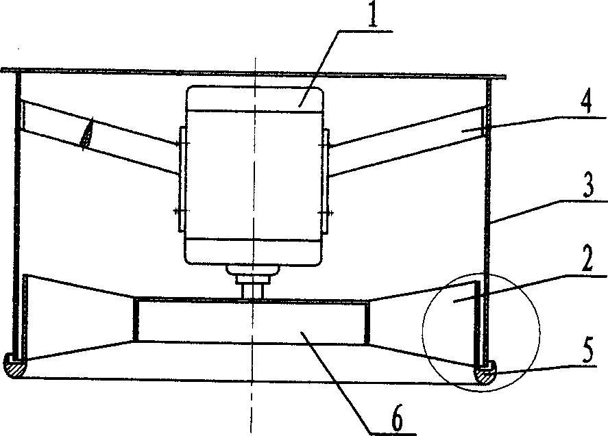
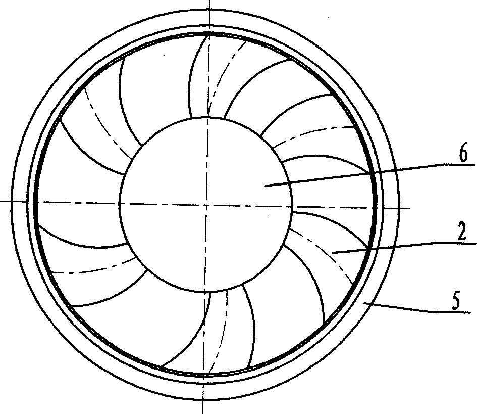
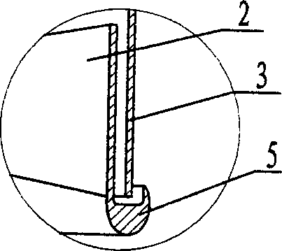
[0017] The structure of the low-noise axial flow fan with rotating guide ring of the present invention is as follows: figure 1 As shown, it includes a motor 1, a fan blade 2, a casing 3, a bracket 4 and a hub 6, the hub 6 is installed at the bottom of the casing 3, the motor 1 is installed above the hub 6 and is coaxially connected with it, and the motor 1 passes through the bracket 4 fixed on the inner surface of the casing 3. The air flow passes through the impeller first, and then the motor. In order to reduce separation and eddy current formation when air flows around the motor support, the cross section of the motor support 4 is designed as a streamlined body. The fan blades 2 are arranged on the hub 6 according to unequal distances. A rotating guide ring 5 that rotates with the blades 2 is provided at the lower inlet end of the casing...


PUM


Abstract

The invention relates to a low noise axial fan with rotating flow guide ring, comprising electric machine, vane, machine casing, bracket and wheel hub, where the wheel hub is arranged at the lower part of the machine casing, the electric machine is arranged above the wheel hub and coaxially connected with the wheel hub and fixed on the inner surface of the machine casing, the section of the bracket is streamlined, the vane is of an integral fixed vane angle profile and of a forward-swept shape, wide outside and narrow inside, and these vanes are not equidistantly arranged, and the link line of gravity centers of various sections of the vane forms an included angle <=30 deg. with its radial straight line. The lower inlet end of the machine casing is provided with rotating flow guide ring rotating with the vanes, the upper cylinder body of the flow guide ring is integrated with the vane circumference, and keeps a rotating gap from the inner diameter of the machine casing, a bottom circular arc flow guide ring is of a 1 / 4 ellipse in shape, and the lower annular end surface of the machine casing is arranged in the flow guide ring and forms an axial gap from a platform in the flow guide ring to be good for relatively rotating. The invention has remarkable noise-reducing and energy-saving effects.

Description

technical field [0001] The invention relates to an axial flow fan, in particular to a low-noise axial flow fan with a rotating guide ring, which is applied to a train air conditioner condenser and belongs to the technical field of fluid engineering. Background technique [0002] With the rapid development of the country's economic construction, urban rail transit is playing a very important role as a city's transportation hub. At present, urban rail transit is developing vigorously and has entered a new period of development. It has become a key project in many cities . Huge construction funds have become a major bottleneck in the development of urban rail transit. The primary problem before us is to adopt domestic technology and equipment, reduce project costs, and promote the rapid development of urban rail transit. The train air conditioner is an important facility on the rail transit train. The train air-conditioning device for urban rail transit requires compact size ...

Claims


Application Information

Patent Timeline
IPC IPC(8): F04D19/00F04D29/38F04D29/64
Inventor 任世瑶任勇方建发吴明生
Owner SHANGHAI JIAO TONG UNIV
Learn More