
Volute Mechanism of a Centrifugal Fan

a centrifugal fan and volute technology, which is applied in the field of range hoods, can solve the problems of reduced fan efficiency and high noise of fans, and achieve the effects of reducing noise, reducing noise, and reducing the resistance to the air flow of the air-guiding block

Active Publication Date: 2019-11-07
NINGBO FOTILE KITCHEN WARE CO LTD
View PDF0 Cites 7 Cited by
  • Summary
  • Abstract
  • Description
  • Claims
  • Application Information

AI Technical Summary

Benefits of technology

The technical effect of the present invention is to improve the efficiency and reduce the noise of a centrifugal fan by eliminating vortex through active noise reduction. This is achieved by providing a volute that eliminates the need for a vortex, reducing fan noise and improving fan efficiency.

Problems solved by technology

Due to the high pressure and complicated flow of gas in the vicinity of the volute tongue, the flow noise and rotation noise generated in the vicinity of the volute tongue are the main noise sources of the centrifugal fan.
However, due to the small space at the volute tongue, it is difficult to completely discharge the gas at one time, and the residual gas is easy to flow back and form vortex.
Consequently, the fan efficiency is reduced, and the vortex noise is generated, so that the fan still has high noise.

Method used


Image

  • Volute Mechanism of a Centrifugal Fan
  • Volute Mechanism of a Centrifugal Fan
  • Volute Mechanism of a Centrifugal Fan

Examples


embodiment 1

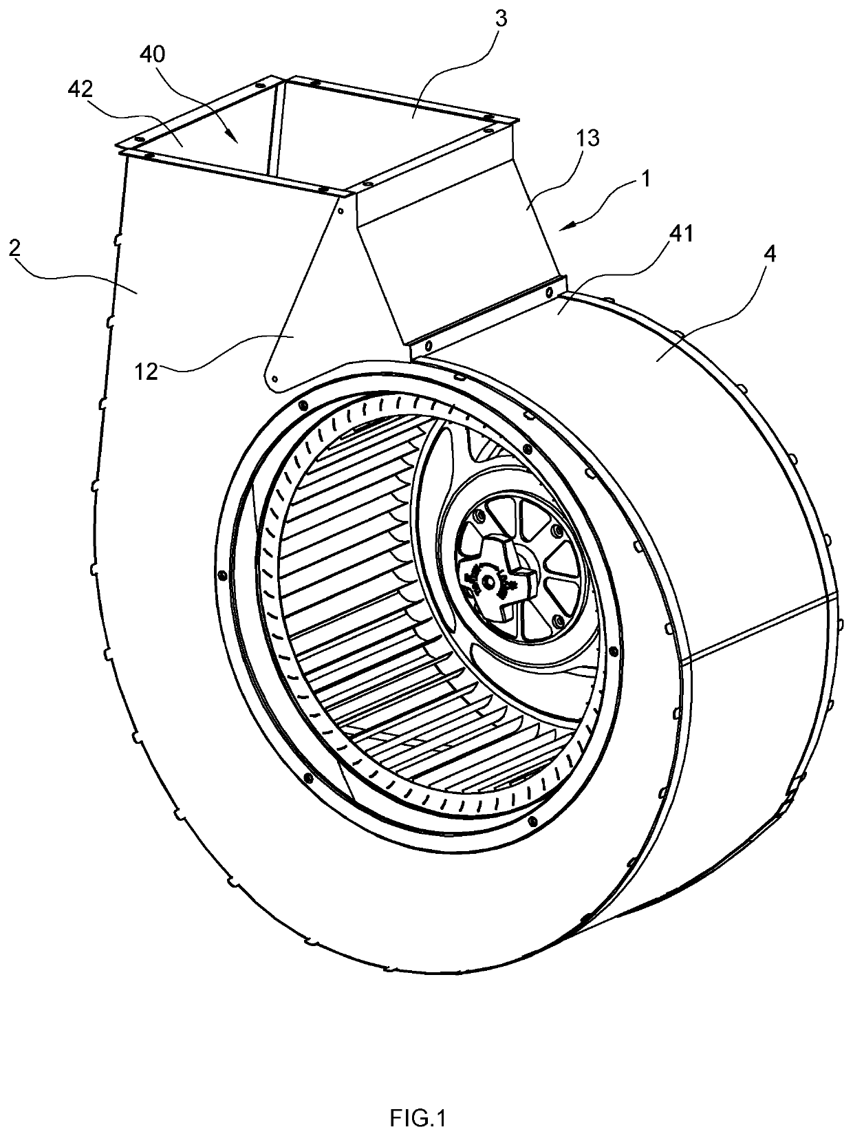
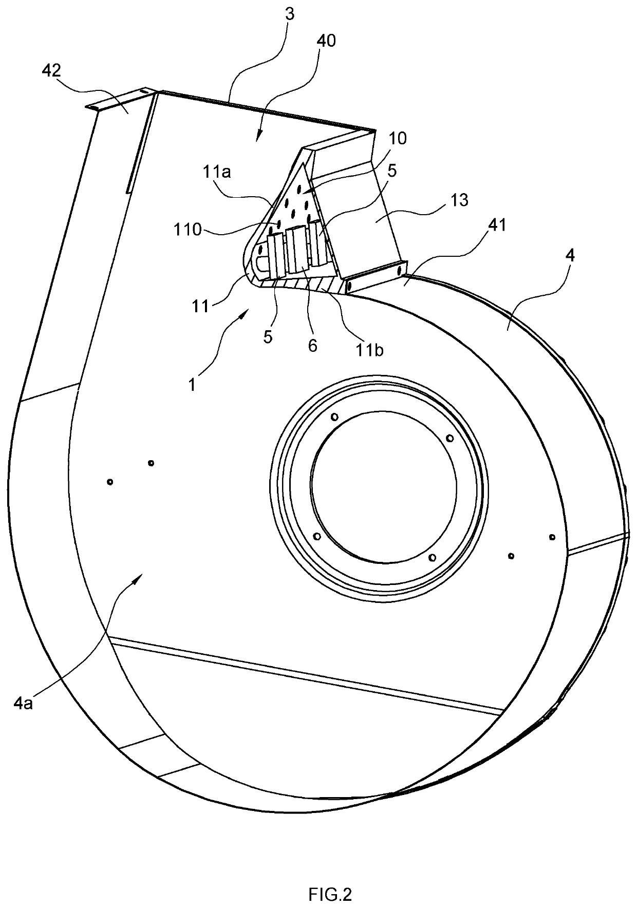
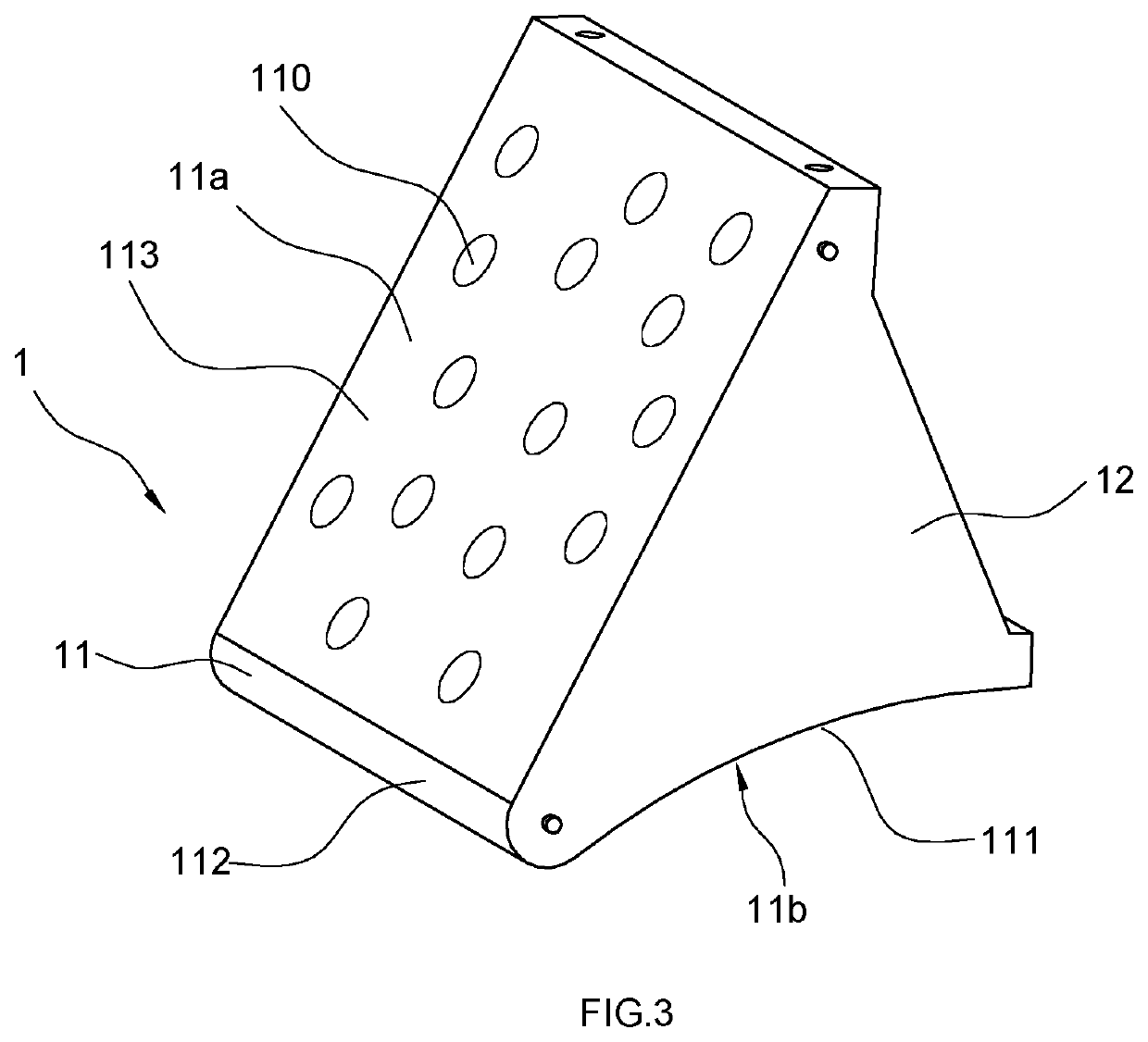
[0031]FIGS. 1-3 show a centrifugal fan with a volute according to Embodiment 1 of the present invention. The volute according to Embodiment 1 comprises a volute tongue 1, a front cover plate 2, a rear cover plate 3, an annular volute wall 4 with a first end 41 and a second end 42, a sound collector and a speaker 6; wherein, the annular volute wall 4 is connected between the front cover plate 2 and the rear cover plate 3; an air flow chamber 4a disposed inside the volute is formed by the front cover plate 2, the rear cover plate 3 and the annular volute wall 4; the volute tongue 1 is connected to the first end 41 of the annular volute wall 4; an air outlet 40 is enclosed by the second end 42 of the annular volute wall 4, the sidewall of the volute tongue 1 opposite to the second end 42 of the annular volute wall 4, the front cover plate 2 and the rear cover plate 3.

[0032]In this embodiment, the volute tongue 1 has a tongue body 11 in L-shaped with a vertical portion 11a and a transve...

embodiment 2

[0035]FIGS. 1, 4-6 show a centrifugal fan of Embodiment 2 with the volute of the present invention. This embodiment differs from Embodiment 1 in that: in this embodiment, volute tongue 1 not only has a tongue body 11, two side plates 12 and a rear plate 13, but also has a L-shaped air-guiding plate 14 having a vertical portion 14a and a transverse portion 14b disposed adjacent to the tongue body 11.

[0036]The vertical portion 14a of the air-guiding plate 14 and the vertical portion 11a of the tongue body 11 are separated with an interval, which forms a narrow air-guiding passage 151, a top 152 of the air-guiding passage 151 is in communication with the air outlet 40; the top 152 is disposed between the vertical portion 14a of the air-guiding plate 14 and the vertical portion 11a of the tongue body 11; and the transverse portion 14b of the air-guiding plate 14 is connected to the transverse portion 11b of the tongue body 11.

[0037]An air-guiding chamber 15 is enclosed by the two side p...


PUM


Abstract

A centrifugal fan, which comprises an air flow chamber disposed inside the volute, an air outlet attached to the air flow chamber and a volute tongue attached to the air outlet; wherein, the volute tongue comprises a tongue body and an enclosed noise-reducing chamber, the tongue body has a plurality of holes for allowing the air flow from the air flow chamber into the noise-reducing chamber; and a sound collector capable of detecting the intensity of noise and a sounder capable of playing sound are disposed in the noise-reducing chamber. The noise is actively reduced and the secondary discharge of the backflow gas is realized, so that the gas backflow is reduced and the vortex is eliminated.

Description

RELATE APPLICATIONS[0001]This application claims benefit to Chinese Patent Application for a volute for a centrifugal fan, 201810418925.6, filed on May 4, 2018. The specification of the application is incorporated here by this reference.FIELD OF THE INVENTION[0002]The present invention relates to the technical field of range hoods, and in particular to a volute for a centrifugal fan.DESCRIPTION OF THE PRIOR ART[0003]For domestic range hoods, air suction and air exhaust are performed by multi-blade centrifugal fans. A fan generally consists of a volute, a motor, an impeller and the like. A tongue-like protrusion in the volute is called a volute tongue which mainly functions to isolate the flowing gas and prevent the gas from circulating in the volute. Due to the high pressure and complicated flow of gas in the vicinity of the volute tongue, the flow noise and rotation noise generated in the vicinity of the volute tongue are the main noise sources of the centrifugal fan. Therefore, re...

Claims


Application Information

Patent Timeline
Patent Type & Authority Applications(United States)
IPC IPC(8): F04D29/42F24C15/20F04D29/66F04D29/44F04D29/28
CPCF24C15/20F04D29/422F04D29/4233F04D29/441F04D29/663F04D29/281F04D29/462F04D29/665F04D29/4226F04D29/664
Inventor CHEN, XUBINWENG, JIANSONG
Owner NINGBO FOTILE KITCHEN WARE CO LTD
Learn More