Fan motor

a technology of fan motor and fan body, which is applied in the direction of positive displacement liquid engine, piston pump, liquid fuel engine, etc., can solve the problems of increased cost and weight, increased noise of fan, and insufficient cooling of above-mentioned countermeasures, so as to prevent the occurrence of heat damage and problems, improve the cooling effect, and effectively cool down

Active Publication Date: 2010-06-24
MITSUBISHI HEAVY IND LTD
View PDF6 Cites 10 Cited by
  • Summary
  • Abstract
  • Description
  • Claims
  • Application Information

AI Technical Summary

Benefits of technology

[0029]According to the present invention, since the securing parts (securing bolts and the like) for the motor and / or the heat shield panel secured to and supported at the motor holding part are provided at locations closer to the inner circumference side than the outer circumference portion of the heat shield panel, the securing parts for the heat shield panel itself, which is exposed to a heat source, and for the motor, which generates heat by itself, can be effectively cooled by cooling air guided to the inner face side of the heat shield panel. Therefore, it is possible to reliably prevent the occurrence of heat damage and problems caused by external radiation heat and by self-heating.
[0030]According to the present invention, while discrete frequency noise caused by pressure interference between the air guiding part and the fan blades is being suppressed, cooling air can be effectively guided between the motor and the heat shield panel to further improve the cooling effect in the vicinity of the motor. It is thus possible to achieve both an improvement in a self cooling function of the fan motor and a reduction in fan noise, and to reliably prevent the occurrence of heat damage, problems, and the like caused by external radiation heat and by self-heating, fan noise, and deterioration in fan performance and in fan efficiency.

Problems solved by technology

However, when a further increase in temperature in the vicinity of the fan motor is caused by the high density in the engine compartments of recent vehicles, the above-mentioned countermeasures may be insufficient for cooling.
If heat measures and cooling measures are insufficient, a problem may occur due to heat damage, the cost and weight may increase, and in addition, fan noise may increase, and fan performance and fan efficiency may deteriorate.

Method used


Image

  • Fan motor
  • Fan motor
  • Fan motor

Examples


first embodiment

[0062]Hereinafter, a first embodiment of the present invention will be described with reference to FIGS. 1 to 3.

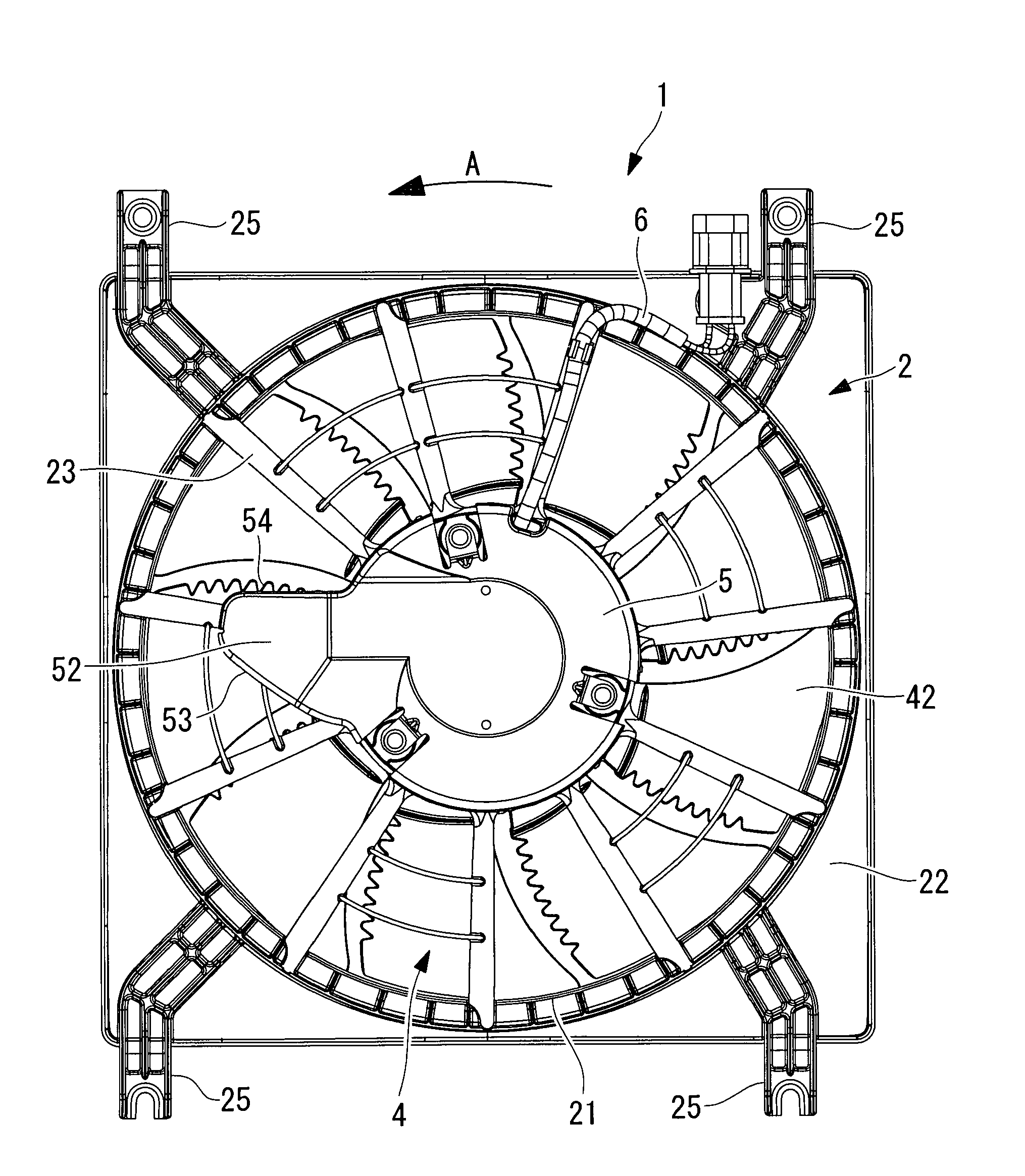
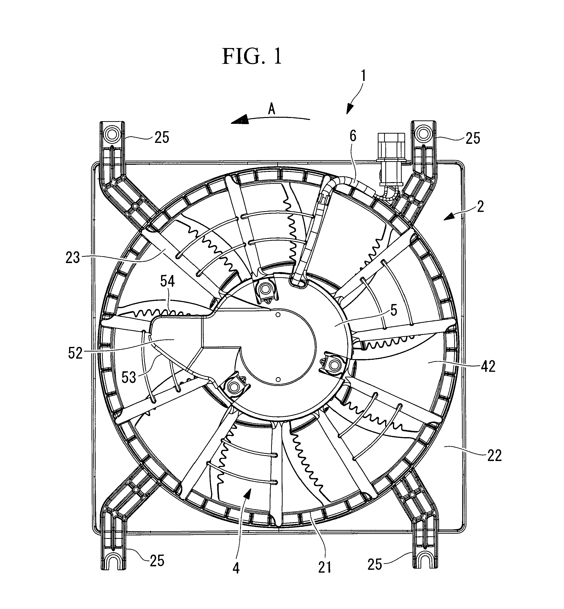
[0063]FIG. 1 is a side view of a fan motor 1 according to the first embodiment of the present invention when seen from a heat shield panel side. FIG. 2 is a longitudinal sectional view of a center portion of the fan motor 1.

[0064]The fan motor 1 includes a shroud 2, a compact electric motor 3 (see FIG. 2) which is secured to and supported at a center portion of the shroud 2, an axial-flow fan 4 which is rotated and driven by the motor 3, and a heat shield panel 5 which shields the rear side of the motor 3 from heat.

[0065]As shown in FIG. 1, the shroud 2 includes a square-shaped frame-like main body 22 which has an opening 21 for letting air in, a motor holding part 24 (see FIG. 2) which is supported at a center portion of the opening 21 by multiple support struts 23 radially provided on the frame-like main body 22, and mounting legs 25 which are provided at the corners of ...

second embodiment

[0077]Next, a second embodiment of the present invention will be described with reference to FIG. 4.

[0078]This embodiment is different from the first embodiment in that guide parts 56 and 57 are provided on the air guiding part 52. Since the other items are the same as those in the first embodiment, a description thereof will be omitted.

[0079]In this embodiment, as shown in FIG. 4, the guide part 56 bent toward the upstream side in an air flow direction B, specifically, in a direction in which outlet air is blown out from the axial-flow fan 4, is provided on the fan-rotational-direction leading edge part 53 of the air guiding part 52, and the guide part 57 bent toward the downstream side in the air flow direction B, specifically, in the direction in which outlet air is blown out from the axial-flow fan 4, is provided on the fan-rotational-direction trailing edge part 54.

[0080]With this configuration, outlet air blown out from the axial-flow fan 4 can be guided to the air guiding par...

third embodiment

[0081]Next, a third embodiment of the present invention will be described with reference to FIGS. 5A to 5C.

[0082]This embodiment is different from the first and second embodiments in that the air guiding part 52 is provided at each of multiple locations. Since the other items are the same as those in the first and second embodiment, a description thereof will be omitted.

[0083]Whereas the above-described embodiments provide the air guiding part 52 at one location on the outer circumference portion of the heat shield panel 5, as shown in FIG. 5A, this embodiment provides the air guiding part 52 at each of two locations at a predetermined pitch angle, as shown in FIG. 5B or provides the air guiding part 52 at each of three locations at a predetermined pitch angle, as shown in FIG. 5C.

[0084]With this configuration, when cooling performance needs to be improved in order to cope with an increase in capacity of the fan motor 1 or an increase in installation environment temperature, the coo...


PUM


Abstract

The present invention provides a fan motor capable of achieving both an improvement in a self cooling function of the fan motor and a reduction in fan noise, and of preventing the occurrence of heat damage, problems, and the like caused by external radiation heat and by self-heating, fan noise, and deterioration in fan performance and in fan efficiency. The fan motor (1) includes: a shroud (2); a motor (3) secured to and supported at the shroud (2); an axial-flow fan (4) connected to a rotation shaft part of the motor (3); and a heat shield panel (5) mounted at the rear side of the motor (3) with a gap being provided therebetween, in which the heat shield panel (5) has a spatula-shaped air guiding part (52) projecting outward in a radial direction at at least one location on an outer circumference portion; and the air guiding part (52) has a width gradually reducing toward an outer side and a fan-rotational-direction leading edge part (53) having an arc shape.

Description

TECHNICAL FIELD[0001]The present invention relates to a fan motor in which a fan and a motor are combined and which is used to cool a radiator, a condenser, and the like for a vehicle.BACKGROUND ART[0002]In a vehicle having an air conditioner, a radiator which cools coolant for the engine and a condenser for the air conditioner may be combined and installed in the engine compartment located behind a front grill of the vehicle. In the radiator and the condenser, a fan motor obtained by combining a fan and a motor is included to let cooling air flow. The fan motor generally includes a plastic shroud which has an opening for letting air in and a motor holding part supported by a plurality of support struts at a center portion of the opening; a compact motor which is secured to and supported at the motor holding part of the shroud; and a plastic axial-flow fan which has a hub part connected to a rotation shaft part of the motor and which has a plurality of fan blades on the outer circum...

Claims


Application Information

Patent Timeline
Patent Type & Authority Applications(United States)
IPC IPC(8): F04D29/58
CPCF04D25/082F04D29/5853F04D29/584F04D29/384F05D2240/304F04D29/5806
Inventor SUZUKI, ATSUSHIKOBAYASHI, TAKAYUKIKAMIYA, KAZUYUKIENYA, YUUKOHIRANO, TAKAYUKI
Owner MITSUBISHI HEAVY IND LTD
Why Eureka
Try Eureka