Home cooking appliance having a flue boundary

a technology of flue boundary and home cooking, which is applied in the direction of domestic stoves or ranges, heating types, lighting and heating apparatus, etc., can solve the problems of increasing manufacturing costs, and achieve the effects of reducing manufacturing costs, reducing manufacturing costs, and reducing manufacturing costs

Active Publication Date: 2015-09-17
BSH BOSCH & SIEMENS HAUSGERAETE GMBH
View PDF8 Cites 8 Cited by
  • Summary
  • Abstract
  • Description
  • Claims
  • Application Information

AI Technical Summary

Benefits of technology

[0025]In this way, the features of the present invention can manage and dissipate the hot air being exhausted from the appliance to minimize or prevent convective heat transfer from flue gases to the back wall of the kitchen. As explained above, the present invention can provide a home cooking appliance having a rear vent trim that is substantially flush with an upper surface of the rear end of the cooking surface, thereby providing a low-profile and compact appliance that provides a “built-in” appearance that is desirable to a user. The flush design maximizes an amount of cooktop cooking surface. At the same time, the present invention can provide a home cooking appliance having a flue boundary a rear vent trim that manages heat by directing the flow of air forward away from a combustible back wall of the kitchen, which faces the rear wall of the appliance, while simultaneously reducing turbulence above the cooking surface, thereby minimizing temperatures on the combustible back wall of the kitchen and improving compliance with industry standards and regulations. The home cooking appliance also can reduce temperatures on other components, such as wall cabinets mounted on the back wall of the kitchen either over the cooking surface of the home cooking appliance or over the adjacent floor cabinets, and / or on another appliance or component, such as an over-the-range (OTR) microwave oven or OTR convection microwave oven, thereby improving compliance with industry standards and regulations. Additionally, the home cooking appliance can manage and dissipate the hot air being exhausted from the appliance in a manner that contributes to a reduction in temperatures on surfaces or components of the home cooking appliance itself, such as temperatures on an oven door, thereby improving compliance with industry standards and regulations.
[0026]The features of the present invention also can manage and dissipate the hot air being exhausted from the appliance without interfering with the operation of the gas burners, thereby improving combustion at the gas burners. Particularly, the features of the present invention can increase an air flow for heat removal and dissipation without increasing the air flow over the burners, thereby avoiding interference with the operation of the burners, such as blowing out the burners. The features of the present invention also can reduce a pressure build-up around the flue outlet of the appliance, thereby avoiding interference with the operation of the flue and maintaining an acceptable combustion in the cooking compartment.
[0027]Moreover, the features of the present invention can increase an air flow for heat removal and dissipation without increasing a fan speed, and thus, without increasing fan noise.
[0028]The features of the present invention can be provided separately, or in combination with each other or in combination with other features of a home cooking appliance for managing and dissipating the hot air being exhausted from the appliance, thereby further improving compliance with industry standards and regulations.
[0029]The features of the present invention are not limited to any particular type of cooking appliance or to a cooking appliance having any particular arrangement of features. For example, one of ordinary skill in the art will recognize that the features of the present invention are not limited to a slide-in gas cooking appliance, and can include, for example, a built-in cooking appliance such as a gas range or gas oven, an electric range or oven, or another cooking appliance that will benefit from directing the flow of air forward away from a combustible back wall of the kitchen or another component, while simultaneously reducing turbulence above the cooking surface, thereby minimizing temperatures on the combustible back wall of the kitchen or another component, and improving compliance with industry standards and regulations.

Problems solved by technology

However, such conventional dilution flues typically require a large amount of space in the housing of the appliance, along with special tooling and expensive components, thereby resulting in increased manufacturing costs.

Method used


Image

  • Home cooking appliance having a flue boundary
  • Home cooking appliance having a flue boundary
  • Home cooking appliance having a flue boundary

Examples


Embodiment Construction

[0060]The present invention now is described more fully hereinafter with reference to the accompanying drawings, in which embodiments of the invention are shown. This invention may, however, be embodied in many different forms and should not be construed as limited to the embodiments set forth herein; rather, these embodiments are provided so that this disclosure will be thorough and complete, and will fully convey the scope of the invention to those skilled in the art.

[0061]Referring now to the drawings, FIGS. 1-11B illustrate exemplary embodiments of a home cooking appliance having a flue boundary and cooling rough-in box.

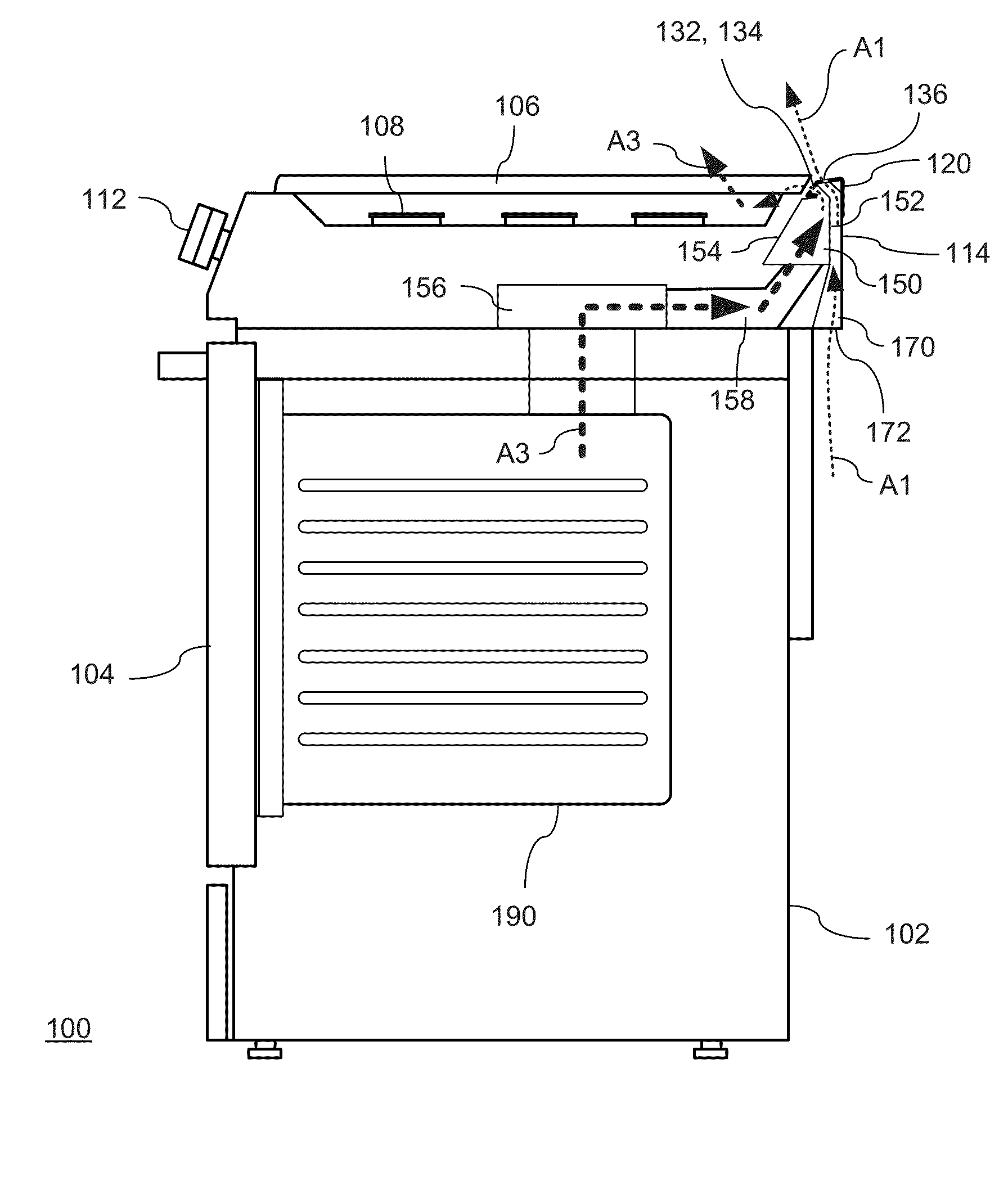
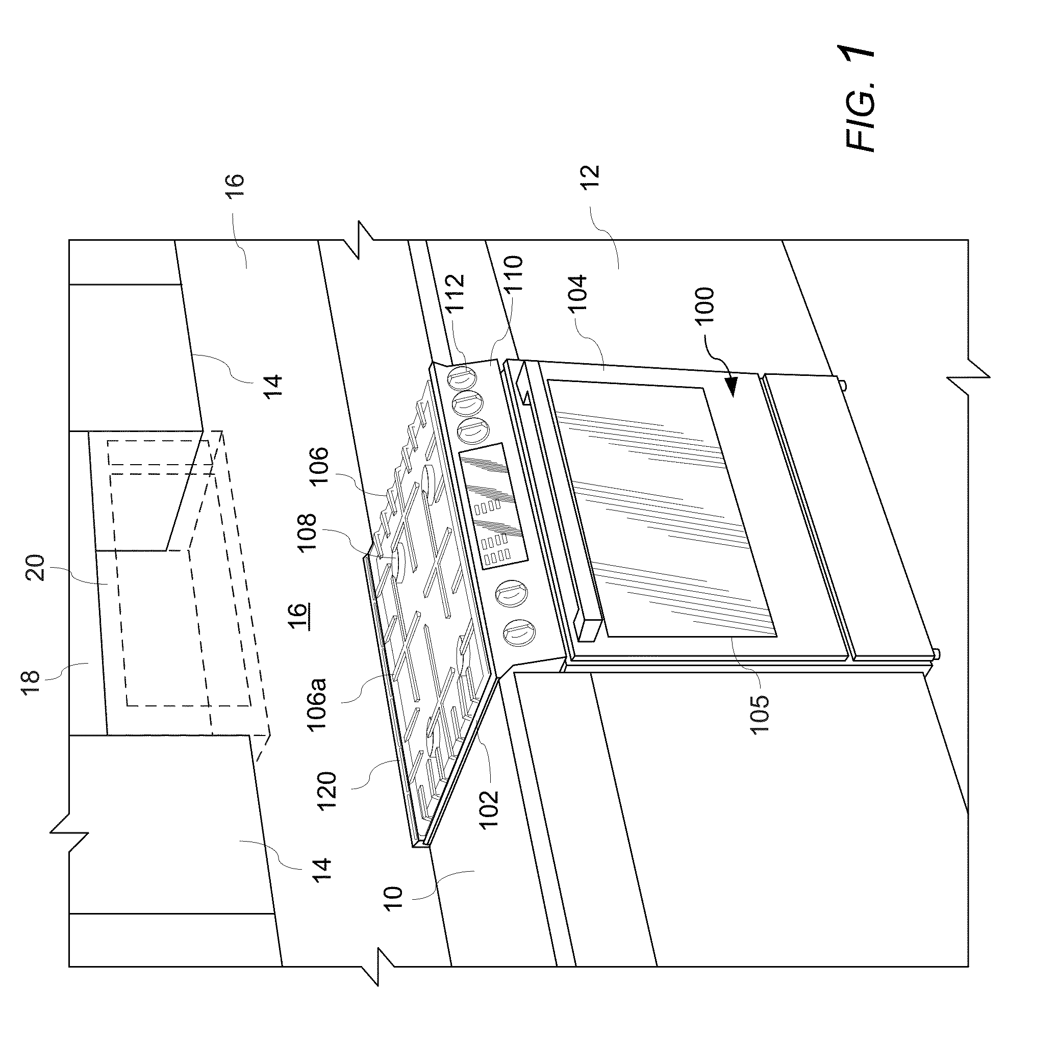
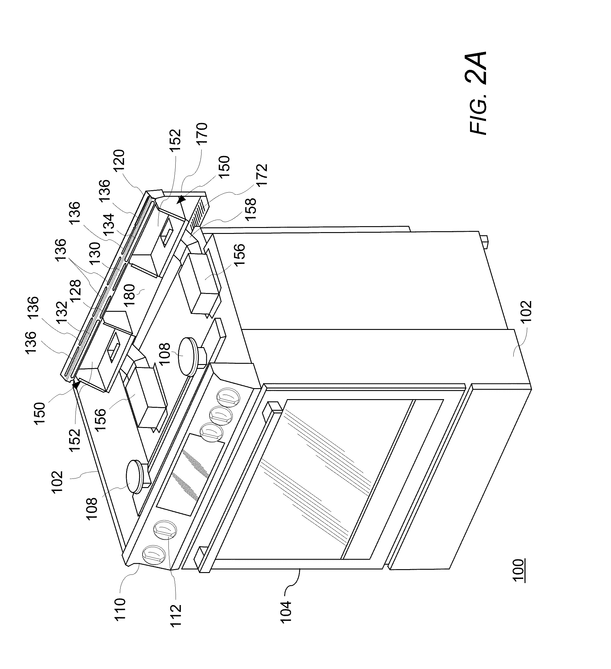
[0062]With reference to FIG. 1, a cooking area of a home kitchen may include counters 10 with floor cabinets 12 below the counters 10. The kitchen can include wall cabinets 14 on back wall 16 (e.g., a combustible back wall). A home cooking appliance 100, such as a slide-in home cooking appliance, can be disposed between the floor cabinets 12 and counters 10. A wa...


PUM


Abstract

A home cooking appliance includes a housing, a cooking compartment in the housing, a flue in the housing and in fluid communication with the cooking compartment for exhausting flue gases from the cooking compartment, an exhaust outlet for exhausting the flue gases from the housing, and a flue boundary connecting the flue and the exhaust outlet, the flue boundary separating flue gases from cooling air flowing through the housing and preventing dilution of flue gases with cooling air. The housing includes a cooling rough-in box having a cooling air flow channel for cooling the rear wall of the flue boundary. The cooling rough-in box includes an opening permitting the cooling air to be drawn into the cooling air flow channel from an exterior of the housing by convection owing to heat on the rear wall of the flue boundary.

Description

CROSS-REFERENCES TO RELATED APPLICATIONS[0001]This application is related to Applicants' co-pending U.S. applications, which are filed concurrently herewith, entitled “HOME COOKING APPLIANCE HAVING A LOW-PROFILE REAR VENT TRIM,” Attorney Docket No. 2013P03686US; and “HOME COOKING APPLIANCE HAVING AN AIR CHANNEL,” Attorney Docket No. 2014P00041US, each of which is incorporated herein by reference in its entirety.FIELD OF THE INVENTION[0002]The present invention is directed to a home cooking appliance having a flue boundary connecting a flue and an exhaust outlet of the housing, and more particularly, to a home cooking appliance having a flue boundary separating flue gases from cooling air flowing through the housing and preventing dilution of flue gases with cooling air, and more particularly, to a home cooking appliance having a flue boundary, which separates flue gases from cooling air and prevents dilution of flue gases with cooling air, and a cooling rough-in box having a cooling...

Claims


Application Information

Patent Timeline
Patent Type & Authority Applications(United States)
IPC IPC(8): F24C15/20
CPCF24C15/2042F24C15/2007F24C15/006
Inventor CHADWICK, TEMPLEDYSINGER, DAVIDGEIGER, JOSEPHKNIGHT, BENJAMIN
Owner BSH BOSCH & SIEMENS HAUSGERAETE GMBH
Why Eureka
Try Eureka