Digital noise reduction for motors

a technology of motor noise reduction and digital noise reduction, applied in the field of motor noise reduction, can solve the problems of reduced longevity, reduced heat dissipation, and partial or catastrophic failure, and achieve the effect of reducing fan nois

Inactive Publication Date: 2007-03-01
ASAHI KASEI ELECTRONICS CO LTD
View PDF17 Cites 9 Cited by
  • Summary
  • Abstract
  • Description
  • Claims
  • Application Information

AI Technical Summary

Benefits of technology

[0015] The present invention in one embodiment provides a system for reducing fan noise by approximating a linear drive using a number of transistors in parallel and sequentially deploying the transistors.
[0016] Another embodiment of the present invention provides a scheme to turn on drivers in discrete steps thereby achieving the benefits of the linear controller topology in an efficient manner and without undue power dissipation. One aspect includes approximating a linear slope with digital steps for the coil current rise and fall times.
[0017] One embodiment is a motor controller system for reducing fan noise comprising a plurality of transistors coupled in parallel forming a first transistor segment, and a plurality of transistors coupled in parallel forming a second transistor segment. There is a first fan coil coupled to the first transistor segment on a first end and coupled to a supply voltage of a second end. A second fan coil is coupled to the second transistor segment on a first end and coupled to the supply voltage of a second end. A first sequencing logic section is coupled to each of the transistors in the first transistor segment, wherein the first sequencing logic section sequentially activates and deactivates at least some of the transistors in the first segment. There is also a second sequencing logic section coupled to each of the transistors in the second transistor segment, wherein the second sequencing logic section sequentially actives and deactivates at least some of the transistors in the second segment. A rise time and a fall time of the first fan coil and the second fan coil is controlled so as to avoid abrupt or steep changes. The control of the L / R time constant eliminates or significantly reduces the steep changes such that the rise and fall times of the coil current is substantially linearized. As noted, the number of transistors in the segments may vary. In one embodiment a voltage regulator is coupled to the first coil and the second coil.
[0020] A method for controlling a motor, comprising: coupling at least one transistor segment to at least one motor coil, wherein each transistor segment has a plurality of transistors. The method includes sequentially activating the transistors of the transistor segment thereby sequentially increasing a current flow through the coil, wherein the sequentially activating is done within a turn-on window. Also, sequentially deactivating the transistors of the transistor segment thereby sequentially decreasing a current flow through the coil, wherein the sequentially deactivating is done within a turn-off window. Finally, processing the turn-on window and the turn-off window to provide a linearly controlled rise time and a linearly controlled fall time, thereby eliminating abrupt changes that produce excessive noise. The method may include repeating the steps of sequentially activating and sequentially deactivating for other transistor segments. The number of transistors in the transistor segment can be programmable.

Problems solved by technology

As a result, heat dissipation has become an increasing concern as hotter components are placed into smaller packages and form factors.
Excessive heat is linked to numerous types of component failures that result in reduced longevity, and partial or catastrophic failure.
However in many electronic devices, active cooling is required.
There are a number of problems associated with fans, including acoustic noise, power consumption, and reliability.
While the fan can be operated with no control aspects, it is inefficient and generates considerable noise by simply operating at full speed.
If more cooling is required, the voltage is increased which increases the cooling capability and also the noise.
As is well known in the art, there are limitations to the relationship of fan speed and input voltage such as startup voltage and stalling problems as well as power inefficiencies.
The cooling fan audible noise is an objectionable by-product of moving air to produce convection cooling.
There are several major sources of audible noise in fans, including blade noise, “second harmonic cogging”, as well as commutation noise.
The blade noise and cogging cannot be appreciably influenced by electrical designs.
At higher fan speeds, the blade noise begins to contribute to the total fan noise which typically increases significantly at higher RPMs.

Method used


Image

  • Digital noise reduction for motors
  • Digital noise reduction for motors
  • Digital noise reduction for motors

Examples


Embodiment Construction

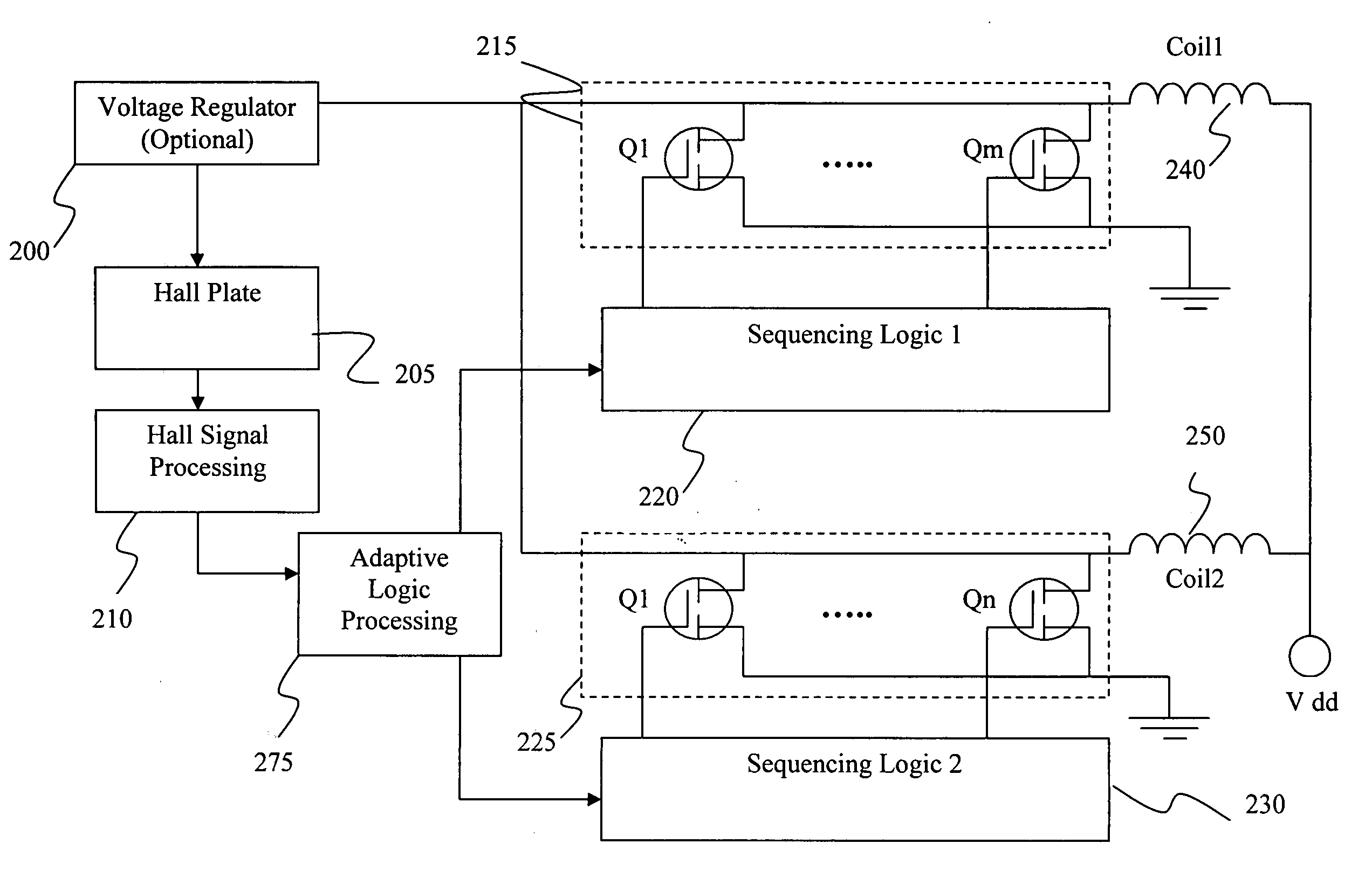
[0042] In a simple form, the present invention reduces noise by controlling the drive current to gradually turn ‘On’ and / or ‘Off’ the motor windings of the fan or other, such as 1 phase motors, 2 phase motors, 3 phase motors and 4 phase motors. In one aspect, the present method approximates a linear drive by using a number of power transistors, such as field effect transistors (FETs), in parallel and sequentially processing the transistors, such that there is a gradual change in drive current between successive steps. As detailed herein, the commutation noise can be reduced by controlling the drive current to gradually turn on the motor windings rather than applying a square wave drive as is typically employed in the art.

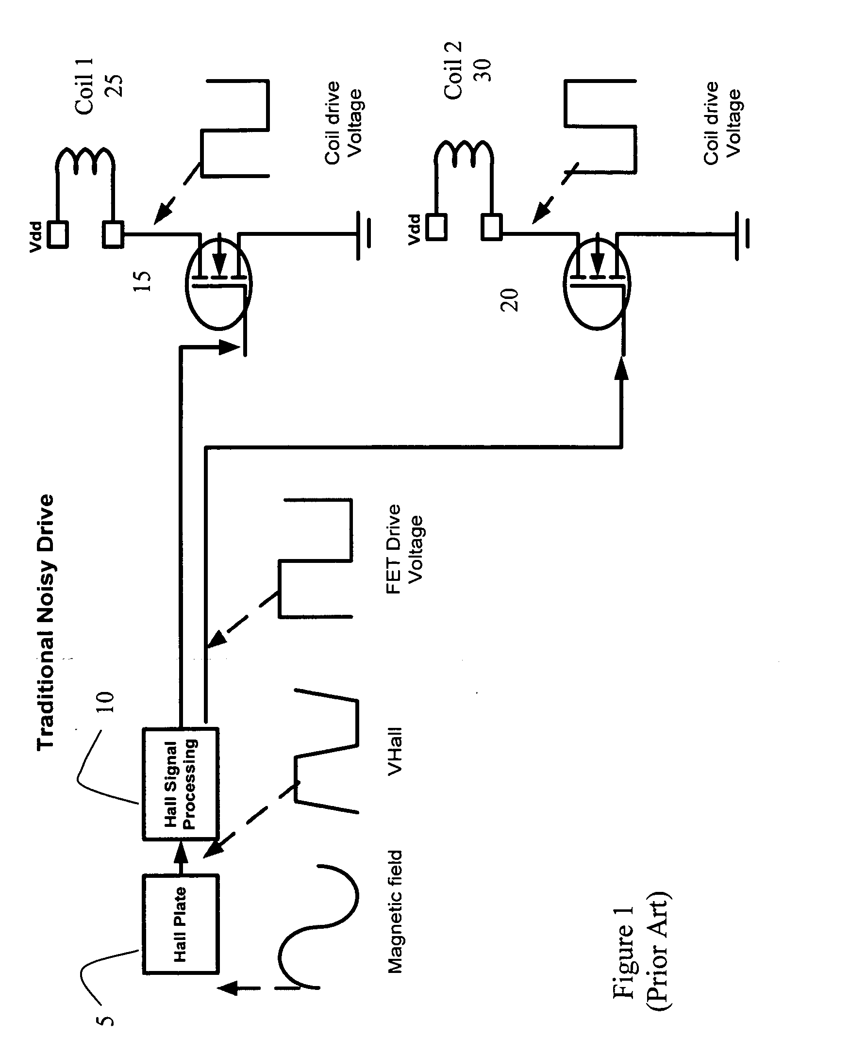
[0043]FIG. 1 show a prior art configuration of a traditional noisy fan control arrangement for a two coil DC motor where the coil drive is a square wave. The fan noise is produced by rapid current changes wherein the dramatic switching of the current ‘On’ and ‘Off’...


PUM


Abstract

A system and method for reducing fan noise by controlling the drive current to the fan motor. In one embodiment the system approximates a linear drive using a number of transistors in parallel and sequentially deploying the transistors. In another embodiment, a scheme is used to activate and deactivate transistors in discrete steps thereby achieving the benefits of the linear controller topology.

Description

RELATED APPLICATIONS [0001] This application claims the benefit of U.S. Provisional Application No. 60 / 712,110, filed Aug. 29, 2005, which is herein incorporated in its entirety by reference.FIELD OF THE INVENTION [0002] The invention relates to motors, and more particularly, to reducing noise of cooling fan motors. BACKGROUND OF THE INVENTION [0003] The general trend in electronic equipment and products is towards faster and smaller products. As a result, heat dissipation has become an increasing concern as hotter components are placed into smaller packages and form factors. Excessive heat is linked to numerous types of component failures that result in reduced longevity, and partial or catastrophic failure. [0004] There are a number of design parameters that are used to dissipate heat and otherwise cool the electronic components. Heat sinks and heat pipes are used as passive mechanisms to remove heat or at least quietly disseminate the heat. However in many electronic devices, act...

Claims


Application Information

Patent Timeline
Patent Type & Authority Applications(United States)
IPC IPC(8): H02P7/06
CPCF04D29/663F04D27/004Y02B30/70
Inventor COLLINS, MARK E.MARSHALL, SUMNER B. III
Owner ASAHI KASEI ELECTRONICS CO LTD
Why Eureka
Try Eureka