Slider with hydraulic cylinder

a hydraulic cylinder and sliding technology, applied in the field of sliding, can solve the problems of affecting the air drag, adjusting the gap too small, and affecting the fuel consumption of the rig, and achieve the effects of enlarge the gap size, high pressure, and fast backward movement of the sliding wheel

Active Publication Date: 2013-01-08
JOST WERKE
View PDF19 Cites 14 Cited by
  • Summary
  • Abstract
  • Description
  • Claims
  • Application Information

AI Technical Summary

Benefits of technology

[0010]Thanks to the motor-operated drive unit, it becomes possible to change the position of the fifth wheel by means of the hydraulic cylinder even during the drive in a feedback control operation. The dimension of the gap, i.e., the size of the intermediate space between the driver's cabin and the trailer, can be adapted individually in dependence on the driving situation, so that the distance during slow driving, for example, when switching payloads, or when parked, can be selected to be large, and when driving fast on the freeway it can be small. The vortices between tractor and trailer can thus be substantially reduced, especially when driving fast. The travel path of the slide or the fifth wheel placed stationary thereon is preferably between 150 mm and 300 mm, especially preferably 200 mm, or optionally 250 mm.
[0023]This design configuration enables very fast reaction times in event of a panic braking and, what is more, it is easy to install, since a pressurized air supply is present in any case on the tractor vehicle and an open pneumatic circuit can be selected.

Problems solved by technology

However, it has been found that the gap or intermediate space arising between the front of the trailer and the cabin of the tractor results in aerodynamic vortices during the drive, which influence the air drag and thus the fuel consumption of the rig.
On the other hand, a gap adjusted to be too small will result, on curves or due to interactions of the payload when braking the rig, to the front of the trailer or its edges knocking against the driver's cabin.
This process requires some skill and can result in serious bodily strain for the drivers.
Furthermore, this is only possible when the vehicle is parked, never during the drive.

Method used


Image

  • Slider with hydraulic cylinder
  • Slider with hydraulic cylinder
  • Slider with hydraulic cylinder

Examples


Embodiment Construction

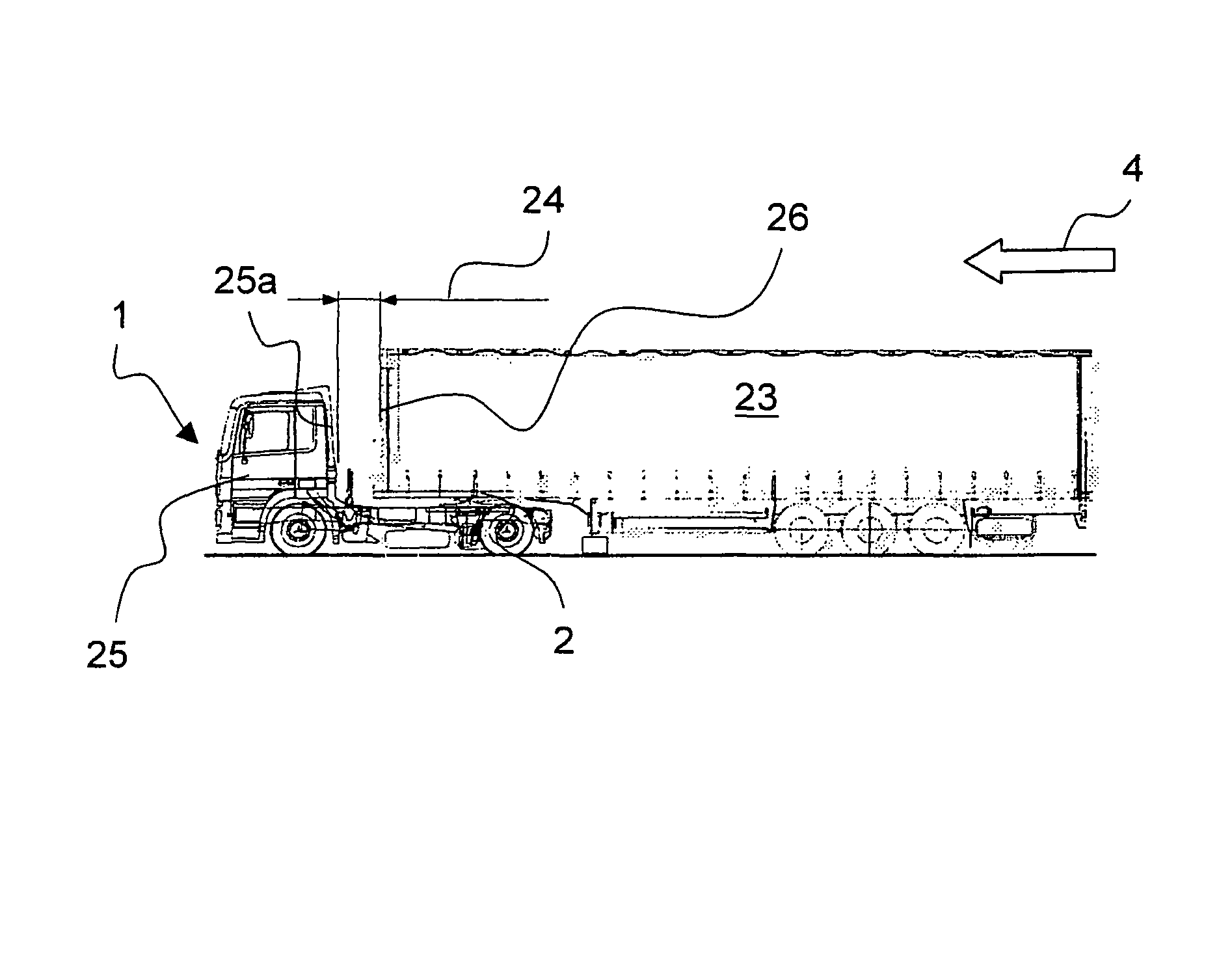
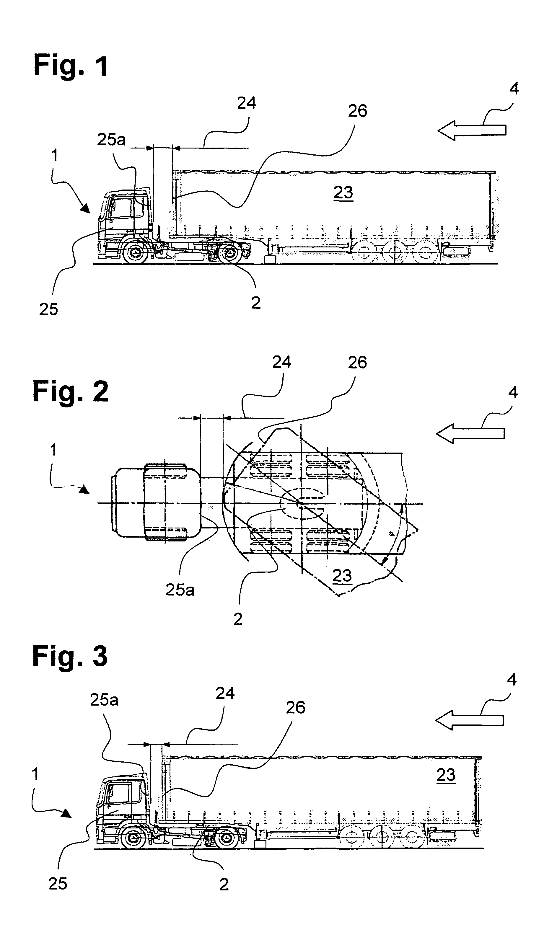
[0042]FIG. 1 shows a side view of a conventional road train with a tractor 1 and a trailer 23 coupled onto it by means of a fifth wheel 2, moving in a straight line. The tractor 1 has a driver's cabin 25, whose rear wall 25a forms a gap 24 with a trailer front 26. In this depicted position of tractor 1 and trailer 23, the gap amounts to around 600 mm.

[0043]The gap 24 is necessary so that a sufficient distance remains between the trailer front 26 and the driver cabin's rear wall 25a, even when the tractor 1 makes a turn, as can be seen in the magnified top view of FIG. 2. When the tractor 1 and trailer 23 are at an angle to each other, the gap 24 is reduced to around 250 mm.

[0044]FIG. 3 shows the road train in a side view, moving in a straight line, where the gap 24 has been considerably reduced by displacing the fifth wheel 2 in the direction of travel 4. This is especially advisable when driving on the freeway, since the driving speed here is high and the anticipated reduction in a...


PUM


Abstract

A slider for a fifth wheel is arranged on a towing vehicle, comprising a substructure with at least two guide rails aligned in the direction of travel, a displaceable slide carrying the fifth wheel and acting upon the guide rails, and a motor-driven drive unit. A slider is provided which allows the gap width between the towing vehicle and the trailer being adapted to the respective driving situation during travel. For this purpose, the slider is characterized in that the motor-driven drive unit is configured from a hydraulic cylinder connected to a hydraulic circuit.

Description

FIELD OF INVENTION[0001]The invention concerns a slider for a fifth wheel arranged on a tractor vehicle, comprising a substructure with at least two guide rails oriented in the direction of travel, a displaceable slide which carries the fifth wheel and engages with the guide rails, and a motor-driven drive unit.BACKGROUND OF THE INVENTION[0002]Sliders are known, for example, from DE-AS 17 80 488, EP 0 503 954 A1, or DE 199 44 684 C1.[0003]Moreover, a slider is known from WO 02 / 070328 A1, which has two guide rails with toothed strips, on which a slide is mounted and able to move, which carries a fifth wheel. A locking mechanism with clamping shoes, engaging with toothed strips, is arranged on the slide.[0004]The sliders which have become known thus far are designed to make an adjustment in regard to the distance between tractor and trailer before the drive begins. However, it has been found that the gap or intermediate space arising between the front of the trailer and the cabin of t...

Claims


Application Information

Patent Timeline
Patent Type & Authority Patents(United States)
IPC IPC(8): B62D53/08
CPCB62D53/0814
Inventor ALGUERA, JOSE MANUELRICHTER, MARTIN
Owner JOST WERKE
Why Eureka
Try Eureka