Method for reconstructing temporary diversion tunnel into permanent flood discharge facility

A diversion tunnel, permanent technology, applied in construction, hydroelectric power station, marine engineering and other directions, can solve problems such as damage, wear and tear of the overflow wall, submerged cave roof, etc., achieve flexible inlet elevation layout, prolong service life, Improve the effect of energy dissipation

A diversion tunnel, permanent technology, applied in construction, hydroelectric power station, marine engineering and other directions, can solve problems such as damage, wear and tear of the overflow wall, submerged cave roof, etc., achieve flexible inlet elevation layout, prolong service life, Improve the effect of energy dissipation

CN105155484AActive Publication Date: 2015-12-16SICHUAN UNIV

Image

  • Method for reconstructing temporary diversion tunnel into permanent flood discharge facility
  • Method for reconstructing temporary diversion tunnel into permanent flood discharge facility
  • Method for reconstructing temporary diversion tunnel into permanent flood discharge facility

Examples


Embodiment 1

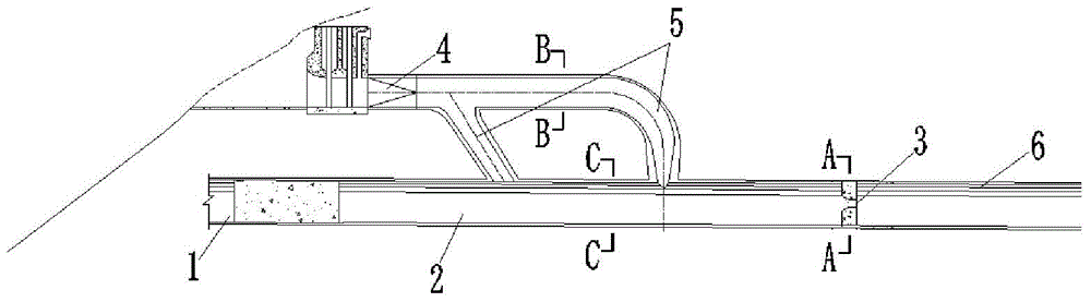
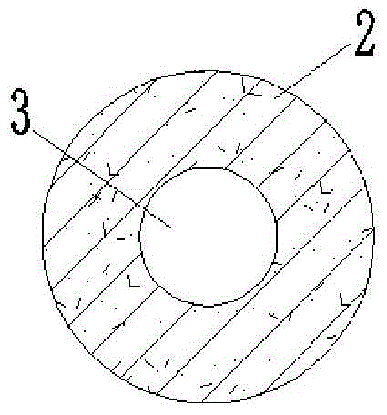
[0028] Such as figure 1 As shown, firstly, the entrance of the original diversion tunnel 1 is blocked, and then the turning section of the entrance and the subsequent straight section 5 times the height of the tunnel are rebuilt into the energy dissipation pressure forebay 2, and the wall surface at the end of the energy dissipation pressure forebay 2 One is set to face the empty jet outlet 3 on all sides, and the section of the jet outlet is circular, see figure 2 , and make the original diversion tunnel section after the jet outlet 3 become the open flow section 6 of the permanent flood discharge tunnel.

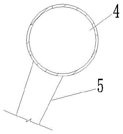
[0029] In this embodiment, a pressurized flood discharge tunnel 4 is newly built at the position above the entrance of the original diversion tunnel 1 that was blocked, and its cross-sectional shape is circular, see image 3 , and the cross-sectional area is smaller than the cross-sectional area of ​​the original diversion tunnel 1, and the bottom elevation of the entran...

Embodiment 2

[0031] Such as Figure 5 , 6 As shown, the entrance of the original diversion tunnel 1 is first blocked, and then the turning section of the entrance and the straight section 7 times the height of the tunnel are rebuilt into the energy dissipation pressure forebay 2, which is in the shape of a city gate. , so a four-sided empty jet outlet 3 is set on the wall of the end, the section of the jet outlet is rectangular, see Figure 7 , and make the original diversion tunnel section after the jet outlet 3 become the open flow section 6 of the permanent flood discharge tunnel.

[0032] In this embodiment, two pressurized flood discharge tunnels 4 are newly built above the entrance of the blocked original diversion tunnel 1, and the entrances of each flood discharge tunnel are arranged along the elevation ladder, and the cross-sectional shape is a city gate shape, see Figure 8 , and the cross-sectional area is smaller than the cross-sectional area of ​​the original diversion tunne...

Embodiment 3

[0034] The difference between the method of rebuilding the temporary diversion tunnel into a permanent flood discharge facility described in this embodiment and embodiment 2 is that: 1) the newly-built flood discharge tunnel 4 is 4, and the entrances of each flood discharge tunnel 4 are arranged along the elevation ladder, Such as Figure 11 2) The connecting pipes 5 are all formed directly after turning at the end of the newly built flood discharge tunnel 4; 3) The total area of ​​the connection between the four connecting pipes 5 and the energy dissipation pressure forebay 2 is equal to the cross-sectional area of ​​the original diversion tunnel 1 ; 4) The two connecting pipes 5 located upstream of the energy dissipation pressure forebay 2 are connected with the top surface of the energy dissipation pressure forebay 2 by the axis, and the two connecting pipes 5 located downstream of the energy dissipation pressure forebay 2 are connected to the energy dissipation pressure for...


PUM


Abstract

The invention provides a method for reconstructing a temporary diversion tunnel into a permanent flood discharge facility. The method comprises the steps that firstly, an entrance of the original diversion tunnel (1) is blocked; secondly, an entrance curve section of the diversion tunnel and a straight section behind the entrance curve section are reconstructed into an energy dissipation pressure forebay (2), and the wall surface of the tail end of the energy dissipation pressure forebay is provided with a jet flow outlet (3), so that the diversion tunnel section behind the outlet becomes a free flow section (6) of a permanent flood discharge tunnel, wherein the straight section is at least five times longer than the entrance curve section; thirdly, at least one flood discharge tunnel (4) is newly constructed at the position above the entrance of the blocked diversion tunnel, wherein the bottom surfaces of entrances of the newly constructed flood discharge tunnels are at least 2m higher than the highest position which silt silting at the entrances can reach; and fourthly, each newly constructed flood discharge tunnel (4) is connected with the energy dissipation pressure forebay (2) through at least one connecting pipeline (5), and the axes of the newly constructed flood discharge tunnels (4) intersect with the axis of the energy dissipation pressure forebay (2). By means of the method, not only can the diversion tunnel with the planar curve section be smoothly reconstructed and utilized, and investment is saved for a whole water conservancy and water power project, but also the energy dissipation effect can be improved, and the service life of a building is prolonged.

Description

technical field [0001] The invention belongs to the technical field of reconstruction of water conservancy and hydropower facilities, and in particular relates to a method for rebuilding a temporary diversion tunnel in a water conservancy and hydropower project into a permanent flood discharge facility. Background technique [0002] During the construction of water conservancy and hydropower projects, it is often necessary to temporarily block the river to facilitate construction in the original river course. At this time, some temporary buildings need to be built to divert the water in the river to the downstream of the construction area. Diversion tunnels are often built Such a temporary structure. In order to save engineering investment, the shorter the length of the diversion tunnel, the better, which leads to the existence of plane turning sections in the diversion tunnel. For such temporary drainage structures, they are generally abandoned after the construction of th...

Claims


Application Information

Patent Timeline
16 Dec 2015
Publication
CN105155484A
IPC
E02B8/06; E02B9/02
CPC
Y02E10/20
Inventors
邓军; 许唯临