
Automatic closing structure of water inlet valve of closestool

An automatic shut-off and water inlet valve technology, applied in water supply devices, flushing equipment with water tanks, buildings, etc., can solve problems such as toilet blockage, flush toilet overflow, toilet flush valve leakage, etc., and achieve the effect of easy installation

Active Publication Date: 2015-12-16
赫林集团公司
View PDF6 Cites 0 Cited by
  • Summary
  • Abstract
  • Description
  • Claims
  • Application Information

AI Technical Summary

Problems solved by technology

This type of toilet water inlet valve and other toilet components often fail, such as obstructions in the toilet drain pipe that cause the toilet to block, causing the toilet to overflow when the toilet is flushed, and then damage the surrounding objects
This known toilet water inlet valve does not provide the function of cutting off the water supply that is beneficial to reduce losses when the water level of the toilet bowl is at a high water level
[0003] In addition, when the liquid level in the toilet water tank of this known toilet water inlet valve reaches the full water level, the water supply cannot be cut off if there is a failure, which will lead to leakage and waste a lot of water resources
Therefore, when the liquid level of the toilet tank reaches a high water level, if the overflowing water cannot be continuously discharged to the auxiliary drainage device provided by the toilet, it will cause the toilet tank to overflow, causing the loss of the surrounding objects again.
[0004] Known toilet flush valves also often break down. For example, the flush valve may be stuck in the open position, causing the liquid level of the water tank to fail to rise all the time, causing the water inlet valve to continuously supply water, resulting in wasting a lot of water resources. In more serious cases, this The toilet flush valve may be leaking, allowing the fluid level in the tank to slowly drop until the float reaches the set point that opens the inlet valve
Normally, the water entering the tank from the inlet valve is much faster than the water leaking from the flush valve, so the float will not close the inlet valve until the tank level rises to the set point, but the flush valve will still Continuous leakage, followed by repeated water injection into the water tank, resulting in wasting a lot of water resources and increasing the user's operating costs
In the known technology, none of the toilet water inlet valves can provide the function of cutting off the water supply to prevent waste when an abnormal condition of the flush valve is detected

Method used


Image

  • Automatic closing structure of water inlet valve of closestool
  • Automatic closing structure of water inlet valve of closestool
  • Automatic closing structure of water inlet valve of closestool

Examples


Embodiment 1

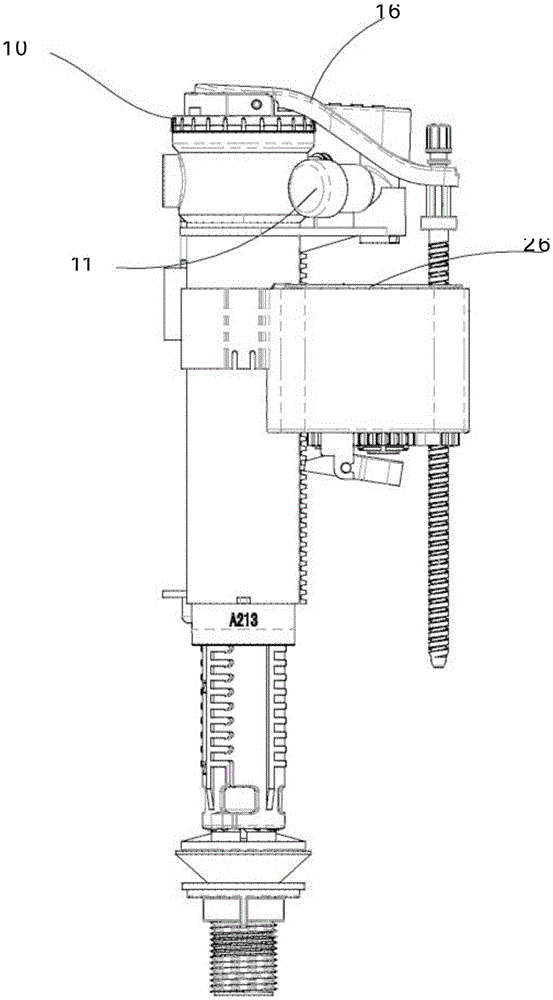
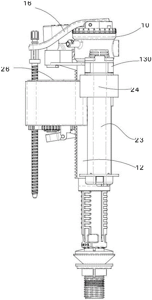
[0045] Example 1: Please see Figure 1-7 , A toilet water inlet valve automatic closing structure, with a water inlet valve floating ball structure 26 that raises the floating arm 16 to correspond to the rising water level 8 of the toilet tank 9. The floating arm 16 uses the water inlet valve floating ball structure 26 Lift up to close the toilet inlet valve 10; also includes:

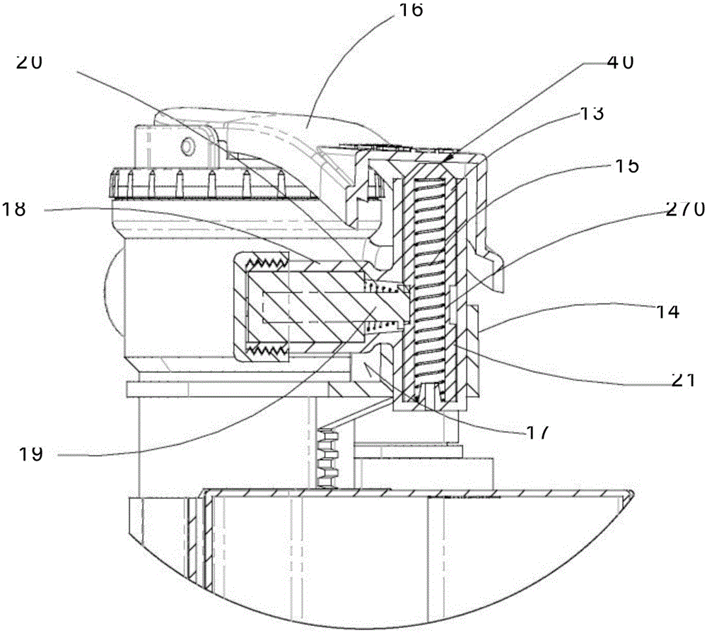
[0046] An auxiliary transmission device 11, the auxiliary transmission device 11 includes a slidable piston 13 perpendicular to the bottom of the floating arm 16, when the piston 13 is in the rising position 50, the floating arm 16 is lifted to fully close the toilet inlet valve 10 ; An eccentric device 15 pushes the piston 13 up to the rising position 50.

[0047] A solenoid structure 18 is usually in a de-energized state, and when the piston 13 is in the lowered position 40, it slidingly engages the locking structure 17 of the piston 13; when energized, the solenoid structure 18 is released from the locki...

Embodiment 2

[0058] Embodiment 2: In this embodiment, except for the eccentric device 15, the rest is basically the same as the above embodiment, so it will not be repeated.

[0059] See Figure 8-9 The eccentric device 15 is a hydraulic structure 200 driven by the water pressure of the toilet inlet valve 10. In this embodiment, the solenoid control valve 210 is usually in a de-energized state, so as to appropriately block the water pressure of the toilet water inlet valve 10 caused by the lifting of the piston 13, so as to facilitate closing the toilet water inlet valve 10. The solenoid structure 211 is a push type instead of the pull type shown in the above embodiment. Both types can be used. The solenoid 211 and the valve core 214 block the toilet inlet valve 10 in its normal position when the power is turned off. The water pressure of the hole 213 can be obtained through the hose 215 from the toilet water inlet valve 10 or other water channels connected to the inlet of the toilet water i...


PUM


Abstract

An automatic closing structure of a water inlet valve of a closestool is provided with a water inlet valve floating ball structure for lifting a floating arm. The floating arm is lifted upwards through the water inlet valve floating ball structure, and thus the water inlet valve of the closestool is closed. The automatic closing structure further comprises an auxiliary transmission device, a solenoid structure and an electronic sensing circuit, wherein the auxiliary transmission device comprises a slidable piston vertically arranged at the bottom of the floating arm and an eccentric device pushing the slidable piston to move upwards, the piston is installed in a piston casing, and the eccentric device is arranged below the piston. The solenoid structure is slidably meshed with a locking structure of the piston. The electronic sensing circuit is provided with at least one sensor and a power supply and electrically connected with the solenoid structure. The automatic closing structure is a device which can detect abnormal conditions such as high water level abnormity of closestools and closestool water tanks, the flush valve blockage at the opening position and flush valve leakage and can automatically close the water inlet valve of the closestool.

Description

Technical field [0001] The invention relates to the technical field of toilets, in particular, it is an automatic closing structure of a toilet water inlet valve. Background technique [0002] The known toilet inlet valve includes an inlet valve float structure that raises a floating arm to correspond to the rising water level of the toilet tank. The float arm is lifted upward by the inlet valve float structure to close the toilet inlet valve . The toilet inlet valve and other toilet components often fail. For example, the obstruction in the toilet drain pipe causes the toilet to be blocked, which may cause the toilet to overflow when the toilet is flushed, and then damage the surrounding objects. This known toilet inlet valve does not provide a water cut-off function that helps reduce losses when the liquid level of the toilet is at a high water level. [0003] In addition, the known toilet water inlet valve cannot cut off the water supply if the liquid level in the toilet tank ...

Claims


Application Information

Patent Timeline
IPC IPC(8): E03D1/32E03D1/33
Inventor 理查德
Owner 赫林集团公司
Learn More