Combined type roof communication tower

A communication pole and combined technology, applied in the direction of towers, roofs, roof coverings, etc., can solve the problems of damage to the roof waterproof layer, less communication antenna mounting capacity, damage, etc., and achieve the goal of improving installation strength and increasing mounting capacity Effect

Active Publication Date: 2015-12-16
HUAXIN CONSULTATING CO LTD
View PDF7 Cites 22 Cited by
  • Summary
  • Abstract
  • Description
  • Claims
  • Application Information

AI Technical Summary

Problems solved by technology

[0002] The new communication antenna on the roof usually uses expansion bolts, anchor bolts, etc. to fix the communication antenna tower on the roof structure layer; but this kind of fixing method will damage the roof waterproof layer, resulting in adverse phenomena such as house leakage, in order to avoid damage to the roof waterproof layer The current common practice is to fix the communication antenna tower on the inside of the parapet wall of the roof
[0003] Although the current design method of directly fixing the communication pole tower on the inner side of the parapet wall of the roof can effectivel

Method used


Image

  • Combined type roof communication tower
  • Combined type roof communication tower
  • Combined type roof communication tower

Examples


Embodiment 1

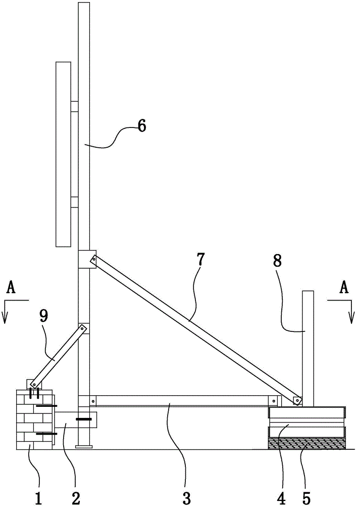
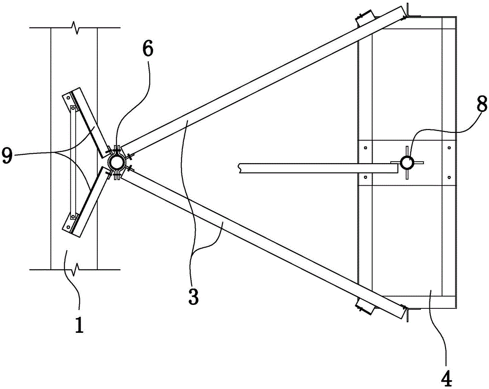
[0030] Embodiment 1: as figure 1 , figure 2 As shown, a combined roof communication pole tower includes a communication pole 6 fixedly arranged on the parapet wall 1 of the roof and a counterweight 4 arranged on the upper surface of the roof. The communication pole is used to mount the communication antenna.

[0031] The parapet is connected with the communication pole through the main supporting structure. The main support structure includes a main support bar 2 and an auxiliary support bar 9 connecting the parapet and the communication pole. One end of the main support rod is connected with the side of the parapet by bolts, and the other end is connected with the lower part of the communication rod. The main support bar is set horizontally. The auxiliary support rod is located above the main support rod. One end of the auxiliary support rod is connected to the top surface of the parapet, and the other end extends obliquely upward toward the communication rod and is con...

Embodiment 2

[0034] Embodiment 2: the remaining structure of this embodiment is with reference to embodiment 1, and its difference is:

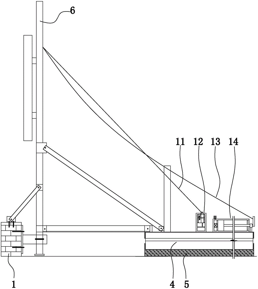
[0035] Such as image 3 As shown, a combined roof communication tower also includes a controller, a trigger rope 11 , a connecting rope 13 , a trigger device 12 and an execution device 14 . The trigger and actuator are located on the same side of the communication pole. The actuator and the parapet are located on opposite sides of the communication pole.

[0036] Such as image 3 , Figure 4 As shown, the trigger device includes a trigger cylinder 121 vertically arranged on the top surface of the counterweight, a trigger piston 123 slidably arranged in the trigger cylinder, and a second trigger piston 123 arranged on the side of the trigger cylinder and below the trigger piston. The lower limit block 122 and the pressure sensor 1213 arranged in the trigger cylinder and above the trigger piston. The pressure sensor is connected with the controller thr...


PUM


Abstract

The invention discloses a combined type roof communication tower. While a roof waterproof layer is prevented from being damaged, mounting strength, firmness and stability of the communication tower can be improved effectively, and then the hanging amount of a communication antenna is increased effectively. The combined type roof communication tower comprises a communication pole and a balancing weight; the communication pole is fixedly arranged on a parapet wall of a roof; the balancing weight is arranged on the upper surface of the roof; a reinforcing supporting structure is arranged between the balancing weight and the communication pole, and comprises a lower supporting rod and an upper supporting rod; the lower supporting rod and the upper supporting rod are connected with the balancing weight and the communication pole; the upper supporting rod is positioned above the lower supporting rod; one end of the upper supporting rod is connected with the middle of the communication pole; the other end of the upper supporting rod slants down, extends to the direction of the balancing weight, and is connected with the balancing weight; one end of the lower supporting rod is connected with the lower portion of the communication pole; and the other end of the lower supporting rod is connected with the balancing weight.

Description

technical field [0001] The invention relates to a communication pole tower, in particular to a combined roof communication pole tower. Background technique [0002] The new communication antenna on the roof usually uses expansion bolts, anchor bolts, etc. to fix the communication antenna tower on the roof structure layer; but this kind of fixing method will damage the roof waterproof layer, resulting in adverse phenomena such as house leakage, in order to avoid damage to the roof waterproof layer The current common practice is to fix the communication antenna tower on the inner side of the parapet wall of the roof. [0003] Although the current design method of directly fixing the communication pole tower on the inner side of the parapet wall of the roof can effectively avoid damage to the roof waterproof layer, the firmness and stability of the communication pole tower directly installed on the inner side of the parapet wall are not good, so the traditional parapet wall att...

Claims


Application Information

Patent Timeline
IPC IPC(8): E04H12/00E04H12/22E04D13/00E04D13/14
Inventor 章跃军田大年姚云龙张珩竹影杨志华孙豪杰胡桂彬
Owner HUAXIN CONSULTATING CO LTD
Why Eureka
Try Eureka