
Multi-functional postpositional transfer case with three output shafts

A transfer case and multi-functional technology, applied in the direction of transmission, gear transmission, transmission control, etc., can solve the problems of unable to provide power output, unable to transfer output, occupying a large space, etc., to achieve smooth and fast shifting, The output power is not affected and the transmission torque is large

Inactive Publication Date: 2015-12-16
YUNMENG POWER PLANT
View PDF8 Cites 1 Cited by
  • Summary
  • Abstract
  • Description
  • Claims
  • Application Information

AI Technical Summary

Problems solved by technology

[0002] The existing rear-mounted transfer case has the defects of fixed speed ratio, which cannot be changed, complicated assembly, inconvenient maintenance, and large space occupation. Moreover, the transfer case can only output an additional power and cannot provide more power output. It is not possible to perform gear shifting operations at will, and it is not possible to engage gears for split output when driving and parking, which cannot meet a wider range of needs.

Method used


Image

  • Multi-functional postpositional transfer case with three output shafts
  • Multi-functional postpositional transfer case with three output shafts

Examples


Embodiment 1

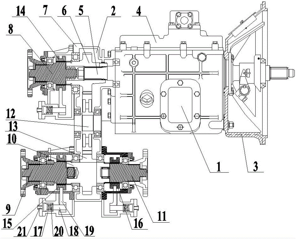
[0024] In the present invention, the multifunctional three-head output post-mounted transfer case, such as figure 1 As shown, it includes a gearbox 1, a transfer case 2 arranged at the rear end of the gearbox 1, and a clutch 3 arranged at the front end of the gearbox 1;

[0025] The gearbox 1 includes a gearbox housing 4 and an input shaft 5. The input shaft 5 is fixedly installed in the gearbox housing 4. One end of the input shaft 5 extends into the transfer case 2 and is sleeved with a first gear 6. The input shaft The other end of 5 stretches into clutch 3;

[0026] The transfer case 2 includes a transfer case housing 7, a first output shaft 8, a second output shaft 9, an intermediate shaft 10, and a third output shaft 11; the first output shaft 8 and the input shaft 5 are coaxially arranged in the transfer case In the housing 7, the end of the first output shaft 8 adjacent to the input shaft 5 is fitted with a first gear sleeve 14 through an external spline, and the end ...

Embodiment 2

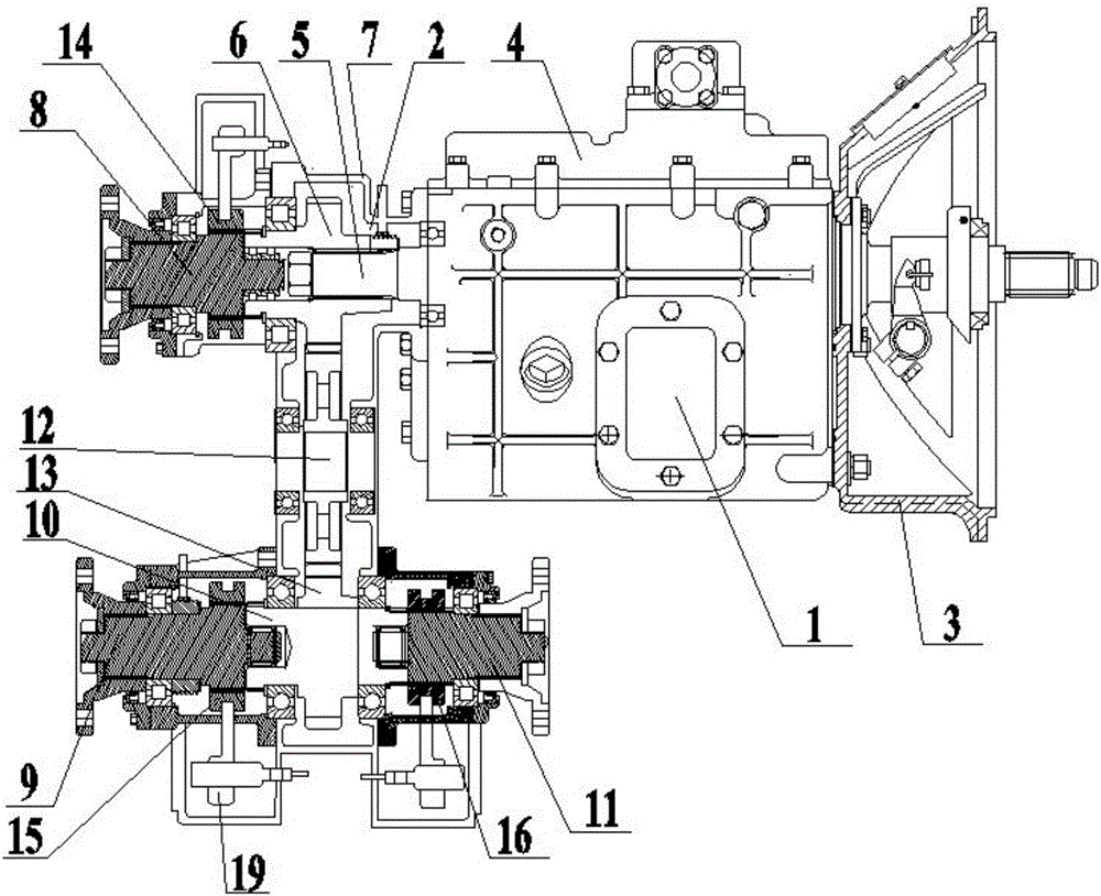
[0029] In the present invention, the multifunctional three-head output post-mounted transfer case, such as figure 2 As shown, it includes a gearbox 1, a transfer case 2 arranged at the rear end of the gearbox 1, and a clutch 3 arranged at the front end of the gearbox 1;

[0030] The gearbox 1 includes a gearbox housing 4 and an input shaft 5. The input shaft 5 is fixedly installed in the gearbox housing 4. One end of the input shaft 5 extends into the transfer case 2 and is sleeved with a first gear 6. The input shaft The other end of 5 stretches into clutch 3;

[0031] The transfer case 2 includes a transfer case housing 7, a first output shaft 8, a second output shaft 9, an intermediate shaft 10, and a third output shaft 11; the first output shaft 8 and the input shaft 5 are coaxially arranged in the transfer case In the housing 7, the end of the first output shaft 8 adjacent to the input shaft 5 is fitted with a first gear sleeve 14 through an external spline, and the end...


PUM


Abstract

The invention discloses a multi-functional postpositional transfer case with three output shafts. The postpositional transfer case comprises a gearbox, a transfer case arranged at the front end of the gearbox, and a clutch arranged at the rear end of the gearbox, wherein an input shaft is fixedly mounted in the gearbox; two ends of the input shaft respectively extend into the clutch and the transfer case; the transfer case comprises a transfer case casing, a first output shaft, a second output shaft, a middle shaft and a third output shaft; a first gear is arranged on the input shaft; a second gear is in meshed connection with the first gear; a third gear is arranged on the middle shaft; the third gear is in meshed connection with the second gear; the input shaft and the first output shaft are arranged coaxially; the second output shaft, the middle shaft and the third output shaft are sequentially arranged coaxially; shifting gear sleeves are respectively connected to the first output shaft, the second output shaft and the third output shaft; corresponding external splines are arranged on the first gear and the third gear respectively; shifting devices are respectively connected to the shifting gear sleeves. The multi-functional postpositional transfer case disclosed by the invention is simple in structure and convenient to maintain, and can independently supply multiple power outputs.

Description

technical field [0001] The invention relates to a speed change device, in particular to a multifunctional three-head output rear transfer case. Background technique [0002] The existing rear-mounted transfer case has the defects of fixed speed ratio, which cannot be changed, complicated assembly, inconvenient maintenance, and large space occupation. Moreover, the transfer case can only output an additional power and cannot provide more power output. Can not arbitrarily put into gear shift operation, can't all put into gear and carry out transfer output when driving and parking, can't satisfy wider demand. Contents of the invention [0003] The purpose of the present invention is to provide a multifunctional three-head output rear-mounted transfer case to solve the problems raised in the above-mentioned background technology. [0004] In order to achieve the above object, the present invention provides the following technical solutions: a multifunctional three-head output...

Claims


Application Information

Patent Timeline
Patent Type & Authority Applications(China)
IPC IPC(8): F16H3/091F16H59/02
CPCF16H3/0915F16H59/02F16H2306/00
Inventor 张应波
Owner YUNMENG POWER PLANT
Learn More