Dynamic repulsion disk and repulsion mechanism using same

A technology of repulsion disk and repulsion coil, which is applied in the direction of contact operating mechanism, power device inside the switch, electrical components, etc., can solve the problems affecting the reliability of the movement of the repulsion mechanism and the low efficiency of the repulsion force, so as to improve the quality of power supply and increase The effect of overall mechanical strength, quick closing and breaking

Active Publication Date: 2015-12-16
PINGGAO GRP +1
View PDF5 Cites 7 Cited by
  • Summary
  • Abstract
  • Description
  • Claims
  • Application Information

AI Technical Summary

Problems solved by technology

This repulsion mechanism has the following problems: due to the skin depth of the eddy current in the dynamic repulsion disk, the induced eddy current is distributed exponentially in the axial direction of the dynamic repulsion disk, and the eddy current is mainly concentrated in the area close to the static repulsion coil, so the dynamic repulsion disk and the static repulsion The output efficiency of the repulsive force generated between the coils is not high, which affects the movement reliability of the repulsive force mechanism

Method used


Image

  • Dynamic repulsion disk and repulsion mechanism using same
  • Dynamic repulsion disk and repulsion mechanism using same
  • Dynamic repulsion disk and repulsion mechanism using same

Examples


Embodiment Construction

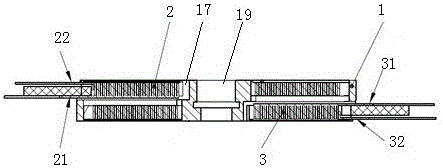
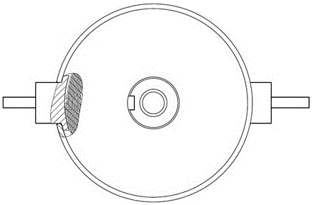
[0033] The specific embodiment of dynamic repulsion disc of the present invention, as Figures 2 to 5 As shown, the dynamic repulsion disk is provided with a central hole 19 extending along the up and down direction for the axis of the transmission rod to be installed. The dynamic repulsion disk includes a disk-shaped skeleton 1 and the first dynamic repulsion coil 2 and the second fixed on the upper and lower sides of the skeleton 1. Two dynamic repulsion coils 3. The skeleton 1 is a disc-shaped structure forged from 45# steel. The first dynamic repulsion coil 2 and the second dynamic repulsion coil 3 have the same structure, and the axes of the two coils coincide with the axes of the central hole 19 . The outer circumference of the center hole 19 on the skeleton 1 is provided with two installation ring grooves 18 for installing the first dynamic repulsion coil 2 and the second dynamic repulsion coil 3, and the two installation ring grooves 18 are distributed along the axial ...


PUM


Abstract

The invention relates to the technical field of power distribution network high voltage switchgear equipment, in particular to a dynamic repulsion disk and a repulsion mechanism using the same. When a dynamic repulsion disk is in use, the dynamic repulsion disk is fixedly connected with a transmission rod; and the dynamic repulsion disk comprises a disk-shaped skeleton, and a first dynamic repulsion coil and a second dynamic repulsion coil fixed on two sides of the skeleton axially. The dynamic repulsion disk adopts a single-disk and double-side dual-coil structure; when the dynamic repulsion disk is in use, the energized dynamic repulsion coil and the corresponding static repulsion coil generate electromagnetic repulsion to drive the transmission rod to move at a high speed; and by using the dynamic repulsion disk, the movement reliability of an operating mechanism can be improved, rapid close and cut-off of circuits can be realized, the impact on systems from an electromagnetic transient effect is reduced, and the power supply quality is improved.

Description

technical field [0001] The invention relates to the technical field of high-voltage switchgear for distribution networks, in particular to a dynamic repulsion disk and a repulsion mechanism using the dynamic repulsion disk. Background technique [0002] In order to further improve the reliability of the high-voltage switch and the rapidity of action, and meet the demand for high-quality, high-safety electric energy, research has been carried out on the repulsion mechanism that relies on electromagnetic repulsion to realize the high-voltage switch at home and abroad. The repulsion mechanism breaks through the mechanism in the traditional sense. The action principle, the excitation time is short, can drive the switch to cut off the fault current in a very short time. [0003] Currently, SF 6 The structure of the repulsion mechanism of the high-voltage switchgear is as follows: figure 1 As shown, the repulsion mechanism includes a dynamic repulsion disk 30, the dynamic repuls...

Claims


Application Information

Patent Timeline
Patent Type & Authority Applications(China)
IPC IPC(8): H01H3/22H01H3/28
CPCH01H3/222H01H3/28
Inventor 李禹生王刚董祥渊卢留洋王海燕何周赵芳帅沙云鹏张洪铁
Owner PINGGAO GRP
Why Eureka
Try Eureka