
Light aircraft flap manipulation device

A control device and light aircraft technology, applied in the field of general aviation, can solve the problems of increased failure rate of flap system, complicated principle, and increased aircraft power load.

Pending Publication Date: 2019-06-21
重庆恩斯特龙通用航空技术研究院有限公司
View PDF0 Cites 4 Cited by
  • Summary
  • Abstract
  • Description
  • Claims
  • Application Information

AI Technical Summary

Problems solved by technology

[0002] The electrical control system in the existing flap system generally includes two independent motors, which increases the load on the aircraft power supply, and the principle of the electrical system driving the mechanical transmission mechanism to rotate is too complicated. The above two aspects will increase the failure rate of the flap system. In order to ensure the safety of the aircraft, it is necessary to invent a simple flap control device that can realize its function and reduce its failure rate

Method used


Image

  • Light aircraft flap manipulation device
  • Light aircraft flap manipulation device
  • Light aircraft flap manipulation device

Examples


Embodiment Construction

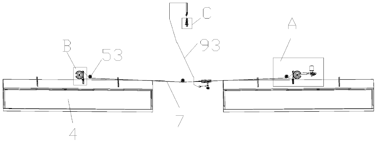
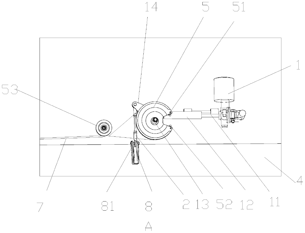
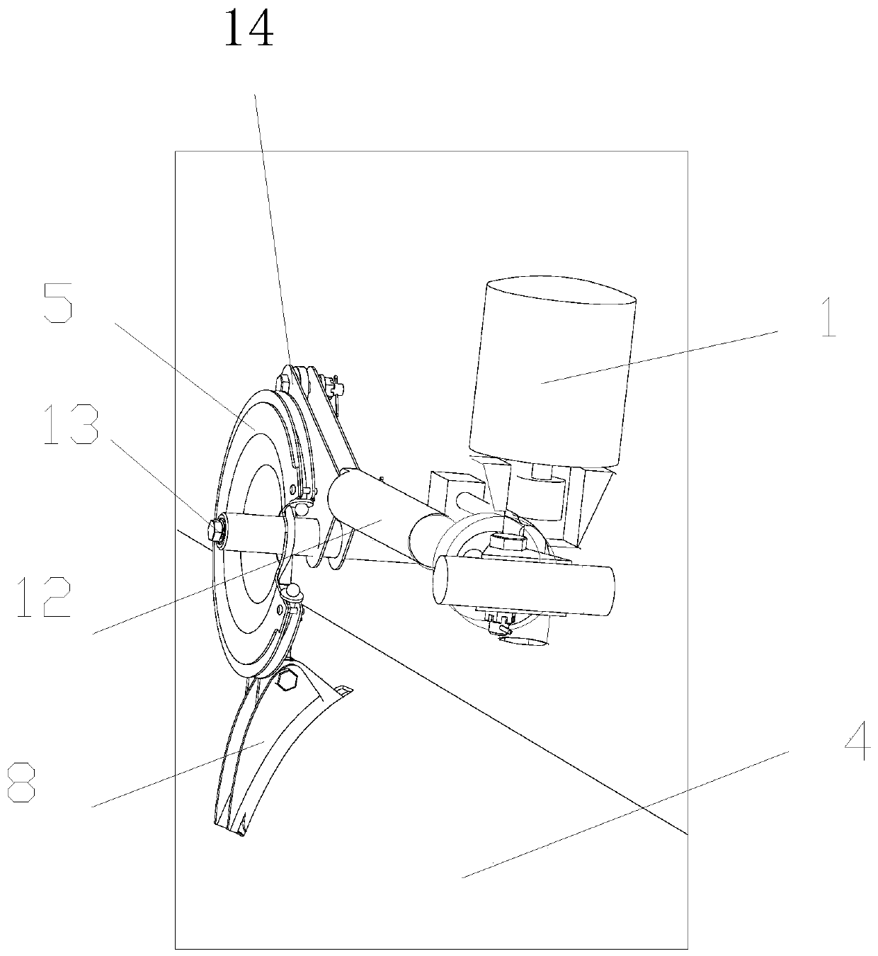
[0033] Attached below Figure 1-7 The present invention is described in further detail.

[0034] A light-duty aircraft flap control device, comprising a flap control handle mechanism, a flap driving mechanism, a flap linkage mechanism and a feedback mechanism, the flap driving mechanism includes a motor 1, the output shaft of the motor 1 is fixedly connected with a worm 11. The outer side of the worm 11 is screwed with a worm shaft cylinder 12, the end of the worm shaft cylinder 12 is hinged with a triangular piece 14, and one end of the triangular piece 14 is fixedly connected with the first rotating shaft 13; the flap linkage mechanism includes a second A pull rod 2 and a second pull rod 3, the first pull rod 2 and the second pull rod 3 are respectively hingedly arranged at the rotation positions of the two flaps 4, the upper end of the first pull rod 2 is hinged with one end of the triangle piece 12, and the first pull rod 2 is hinged with one end of the triangle piece 12. ...


PUM


Abstract

The invention discloses a light aircraft flap manipulation device, wherein a flap driving mechanism comprises a motor, the output shaft of the motor is fixedly connected with a worm, the outer side ofthe worm is screwed and coupled with a worm shaft barrel, and the end of the worm shaft barrel is hinged with a triangle, and one end of the triangle is fixedly connected with a first rotating shaft;a flap linkage mechanism comprises a first pull rod and a second pull rod, the first pull rod and the second pull rod are respectively hinged in two flap rotating positions, the upper end of the first pull rod is hinged with one end of the triangle, the first rotating shaft is fixedly installed with a first fan-shaped rocker, the upper end of the second pull rod is hinged with a connection block,the lower end of the connection block is fixedly installed on a second rotating shaft, the second rotating shaft is fixedly installed with a second fan-shaped rocker, and the first fan-shaped rockerand the second fan-shaped rocker are connected with two guide cables. The device may better reduce the aircraft power load, achieve the synchronous rotation of flaps, reduce the failure rate, and be convenient for maintenance.

Description

technical field [0001] The invention relates to the technical field of general aviation, in particular to a light aircraft flap control device. Background technique [0002] The electrical control system in the existing flap system generally includes two independent motors, which increases the load on the aircraft power supply, and the principle of the electrical system driving the mechanical transmission mechanism to rotate is too complicated. The above two aspects will increase the failure rate of the flap system. In order to ensure the safety of the aircraft, it is necessary to invent a simple flap control device that can realize its function and reduce its failure rate. Contents of the invention [0003] Aiming at the deficiencies of the above-mentioned prior art, the technical problem to be solved by the present invention is: how to provide a light aircraft flap that can better reduce the load of the aircraft power supply, realize the synchronous rotation of the flaps...

Claims


Application Information

Patent Timeline
Patent Type & Authority Applications(China)
IPC IPC(8): B64C13/04B64C13/50
Inventor 卢建涛孙青云曾宪君吴益晓周宝成李宗蓬
Owner 重庆恩斯特龙通用航空技术研究院有限公司
Learn More