Wind turbine pitch-angle control device and method thereof

A control device and pitch angle technology, which is applied in the control of wind turbines, engine control, wind power generation, etc., can solve the problems of increased aerodynamic load and unbalanced load, and achieve the effect of reducing aerodynamic load

Inactive Publication Date: 2010-05-26
MITSUBISHI HEAVY IND LTD
View PDF1 Cites 2 Cited by
  • Summary
  • Abstract
  • Description
  • Claims
  • Application Information

AI Technical Summary

Problems solved by technology

When moving to the feathered position from different pitch angles in this way, there is a problem that the aerodynamic load becomes larger due to the unbalanced load of each windmill blade.

Method used


Image

  • Wind turbine pitch-angle control device and method thereof
  • Wind turbine pitch-angle control device and method thereof
  • Wind turbine pitch-angle control device and method thereof

Examples


Embodiment Construction

[0031] An embodiment of the method and device for controlling the pitch angle of a windmill blade and the windmill according to the present invention will be described below with reference to the accompanying drawings.

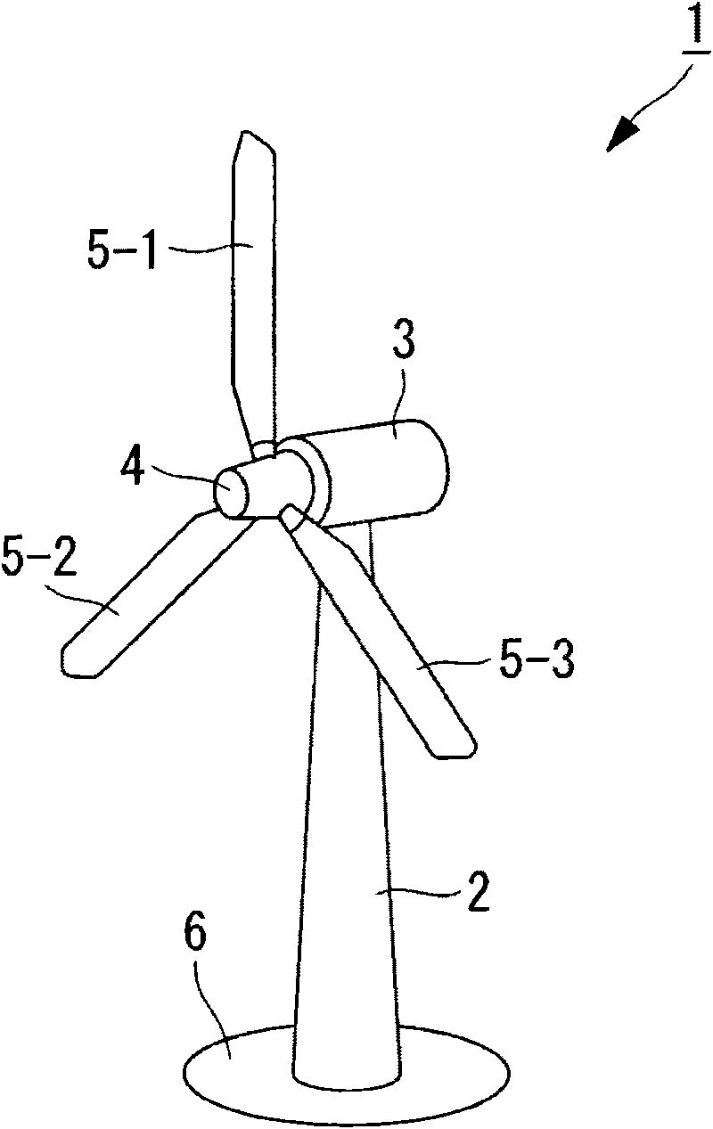
[0032] figure 1 It is a block diagram showing the schematic structure of the windmill of this embodiment. Such as figure 1 As shown, the windmill 1 has: a pillar 2 erected on a foundation 6 , a nacelle 3 arranged on the upper end of the pillar 2 , and a rotor hub 4 provided in the nacelle 3 and capable of rotating around a substantially horizontal axis. The rotor hub 4 is radially mounted with three windmill blades 5-1, 5-2, 5-3 around its axis of rotation. Accordingly, the wind force hitting the wind turbine blades 5-1, 5-2, and 5-3 from the direction of the rotation axis of the rotor hub 4 is converted into power to rotate the rotor hub 4 around the rotation axis. This power is converted into electrical energy by a generator.

[0033] The pitch angle c...


PUM


Abstract

A windmill pitch angle controller which reduces aerodynamic loading at the time of stoppage of a windmill. Upon input of a windmill stop instruction, the windmill pitch angle controller moves a pitch angle of each of windmill wings 5-1, 5-2 and 5-3 to a feathering position after matching the pitch angle of each of the windmill wings 5-1, 5-2 and 5-3.

Description

technical field [0001] The invention relates to a pitch angle control device and method of a windmill independently controlling the pitch angle of the windmill blades. Background technique [0002] Conventional wind turbine control stops the wind turbine when the wind speed becomes higher than the stop wind speed at which the operation is stopped, or when an abnormality such as acceleration or over-power occurs. When the wind turbine is stopped, the pitch angle of the wind turbine blades is moved from the operating state position to the feathered position (for example, refer to Patent Document 1). [0003] Patent Document 1: JP-A-2006-16984 [0004] In the case of employing an independent pitch control method in which the pitch angles of the respective wind turbine blades are individually controlled, the pitch angles of the respective wind turbine blades do not necessarily coincide when the wind turbine is stopped. Therefore, it is also considered to make each windmill bla...

Claims


Application Information

Patent Timeline
Patent Type & Authority Applications(China)
IPC IPC(8): F03D7/04
CPCF03D7/024F05B2270/1095Y02E10/723Y02E10/722F03D7/0244F03D7/043F03D7/0268F03D7/0224F03D7/0264F05B2270/328Y02E10/721F05B2260/74Y02E10/72
Inventor 林义之
Owner MITSUBISHI HEAVY IND LTD
Why Eureka
Try Eureka