Combined compressing apparatus

A compression equipment, combined technology, applied in mechanical equipment, variable displacement pump components, rotary piston pumps, etc., can solve problems such as large size and increased power load

Inactive Publication Date: 2007-07-18
ANEST IWATA CORP
View PDF1 Cites 4 Cited by
  • Summary
  • Abstract
  • Description
  • Claims
  • Application Information

AI Technical Summary

Problems solved by technology

[0003] However, in the known combined compression equipment, a large amount of low-pressure compressed gas is discharged from the turbo compressor as an upstream compressor, so that a large volu

Method used


Image

  • Combined compressing apparatus
  • Combined compressing apparatus
  • Combined compressing apparatus

Examples


Embodiment Construction

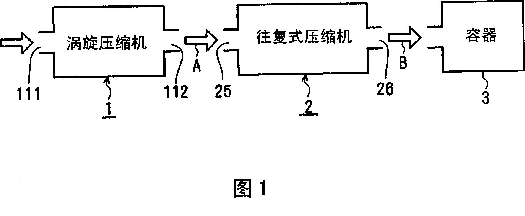
[0009] As shown in FIG. 1, in the combined compressor (combined compressor) according to the present invention, a scroll compressor 1 which is excellent in noiselessness and saves energy is used as an upstream compressor, and has a simple structure and can provide high-pressure reciprocating compressors. Compressor 2 is used as the downstream compressor. The primary compressed gas A compressed by the scroll compressor 1 is delivered to the reciprocating compressor 2 , wherein the primary compressed gas A is further compressed by the reciprocating compressor into a high-pressure secondary compressed gas B to be delivered to the container 3 .

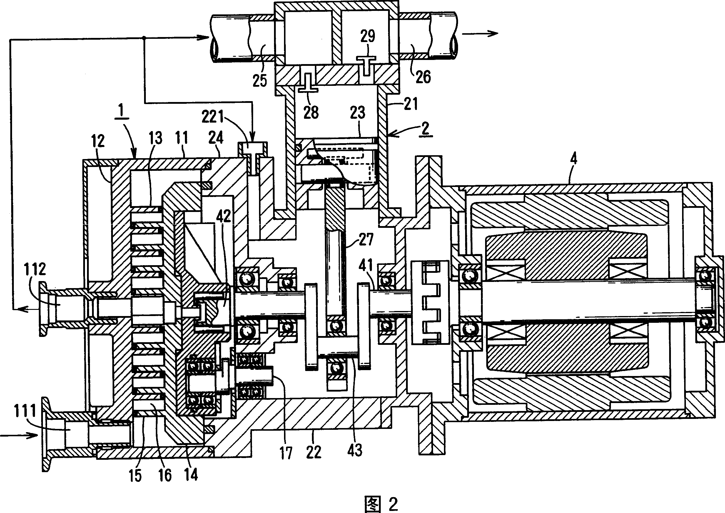
[0010] In FIG. 2 a first embodiment of a combined compression apparatus is shown, wherein the rear part of the cylindrical housing 11 of the scroll compressor 1 is fixed to the front part of the crankcase 22 of the reciprocating compressor 2 . A single engine 4 is mounted to the rear of the crankcase 22 . The engine 4 functions as a powe...


PUM


Abstract

In a scroll compressor, a fixed wrap of a fixed end plate engages with an orbiting wrap of an orbiting plate to form a compressing chamber. A gas is introduced into the compressing chamber from the outer circumference and compressed towards the center as the orbiting end plate revolves with a driving shaft with respect to the fixed end plate. The gas is sent to a reciprocating compressor in which a piston moves up and down in a cylinder and further compressed therein.

Description

technical field [0001] The present invention relates to a combined compression plant for compressing compressed gas discharged from an upstream compressor in a downstream compressor. Background technique [0002] JP2703319B2 discloses a combined compression device in which a turbo-type compressor is used as an upstream compressor, and a volume-type compressor (such as a reciprocating compressor or a scroll compressor) is used as an upstream compressor. as a downstream compressor. The primary compressed gas in the turbo compressor goes to the positive displacement compressor, where it is further compressed and discharged as secondary high pressure compressed gas. [0003] However, in the known combined compression equipment, a large amount of low-pressure compressed gas is discharged from the turbo compressor as an upstream compressor, so that a large volume compressor is used to suck a large amount of primary compressed gas from the turbo compressor, This results in larger...

Claims


Application Information

Patent Timeline
IPC IPC(8): F04B41/00
CPCF04B41/06F04B39/0005F04B39/0094F04B39/12F04C18/0215F04C2240/20F05B2210/12F05B2210/14Y10S417/00
Inventor 井上弘
Owner ANEST IWATA CORP
Why Eureka
Try Eureka