
Cable assembly and power supply connector thereof

A cable assembly and cable technology, applied in the direction of two-part connection devices, connections, circuits, etc., can solve problems such as large resistance, burnt power connectors, and inability to effectively shunt current

Inactive Publication Date: 2015-12-16
ALLTOP ELECTRONICS SU ZHOU +1
View PDF5 Cites 0 Cited by
  • Summary
  • Abstract
  • Description
  • Claims
  • Application Information

AI Technical Summary

Problems solved by technology

Such a setting will cause the current to not be effectively shunted, especially for high-current products, where the connection channel will be the position with the largest resistance and the highest temperature, which may cause power loss or even burn the power connector

Method used


Image

  • Cable assembly and power supply connector thereof
  • Cable assembly and power supply connector thereof
  • Cable assembly and power supply connector thereof

Examples


Embodiment Construction

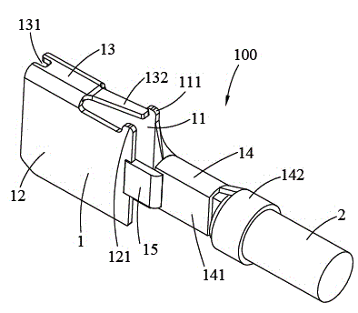
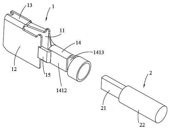
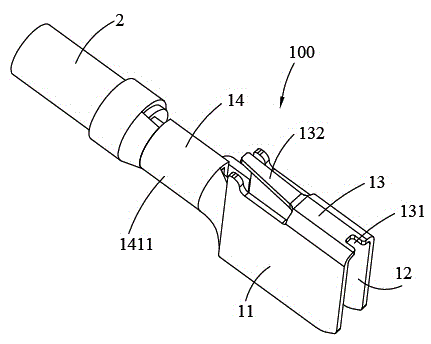
[0021] Please refer to Figure 1 to Figure 5 As shown, the present invention discloses a cable assembly 100 , which includes a conductive terminal 1 and a cable 2 connected to the conductive terminal 1 . The conductive terminal 1 includes a first docking portion 11, a second docking portion 12 arranged parallel to the first docking portion 11, a connecting portion 13 connecting the first and second docking portions 11, 12, and connecting the first and second docking portions 11, 12. The cable joint portion 14 extending from the first docking portion 11 and the overlapping portion 15 connecting the second docking portion 12 and the cable joint portion 14 .

[0022] Both the first docking portion 11 and the second docking portion 12 are located in a vertical plane. The first and second abutting parts 11 and 12 are arranged facing each other. The rear edges of the first and second abutting parts 11 and 12 are provided with positioning protrusions 111 and 121 extending upward. ...


PUM


Abstract

The invention provides a cable assembly and a power supply connector thereof. The cable assembly comprises a conductive terminal and a cable connected to the conductive terminal. The conductive terminal comprises a first butt joint portion, a second butt joint portion parallel to the first butt joint portion, a connecting portion connected to the first and second butt joint portions, and a cable joint portion extending from the first butt joint portion. The conductive terminal also comprises an overlapping portion connected to the second butt joint portion and the cable joint portion. In this way, the first butt joint portion and the second butt joint portion can be both in direct conducting with the cable joint portion to achieve a shunting purpose.

Description

technical field [0001] The invention relates to a cable assembly and a power connector with the cable assembly. Background technique [0002] A power connector in the prior art includes an insulating body and several cable assemblies installed in the insulating body. The cable assembly includes a conductive terminal and a cable connected to the conductive terminal. Wherein, the contact surface of the conductive terminal is usually designed as a ㄇ-shaped structure, which includes two substantially parallel butt joints. Due to the expansion of the terminal material and the receiving of the terminal material, the cable joint can only be designed on one of the butt joints. When the conductive terminal is energized, the docking part directly connected to the cable joint can directly transmit current to the wire, but the docking part not directly connected to the cable joint must communicate with the wire through the ㄇ-shaped connection channel. The current can be transmitted t...

Claims


Application Information

Patent Timeline
Patent Type & Authority Applications(China)
IPC IPC(8): H01R13/02H01R24/00
Inventor 郑义宏刘阔正吴尚明
Owner ALLTOP ELECTRONICS SU ZHOU
Learn More