Radiator for collecting waste heat energy of air compressor and collecting method thereof

A technology of heat energy collection and air compressor, which is applied in the direction of machines/engines, mechanical equipment, liquid variable capacity machinery, etc., and can solve the problems of unsatisfactory collection and inability to collect waste heat energy, etc.

Pending Publication Date: 2019-01-01
QUZHOU CHUANTE ELECTRONICS TECH CO LTD
View PDF8 Cites 0 Cited by
  • Summary
  • Abstract
  • Description
  • Claims
  • Application Information

AI Technical Summary

Problems solved by technology

[0004] In view of the deficiencies in the prior art, the purpose of the present invention is to provide a radiator for collecting waste heat energy of an air compressor and a collection method thereof, aiming at solving the problem...

Method used


Image

  • Radiator for collecting waste heat energy of air compressor and collecting method thereof
  • Radiator for collecting waste heat energy of air compressor and collecting method thereof
  • Radiator for collecting waste heat energy of air compressor and collecting method thereof

Examples


Embodiment 1

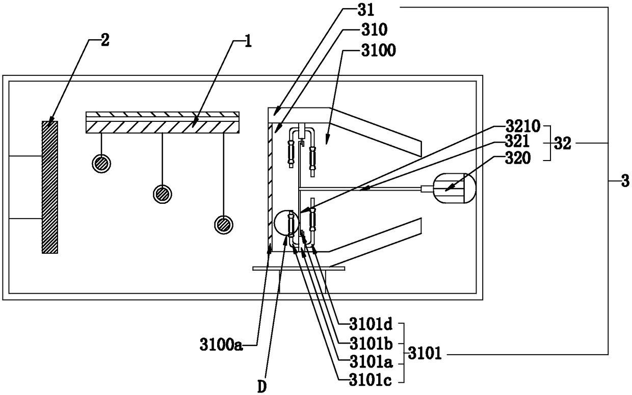
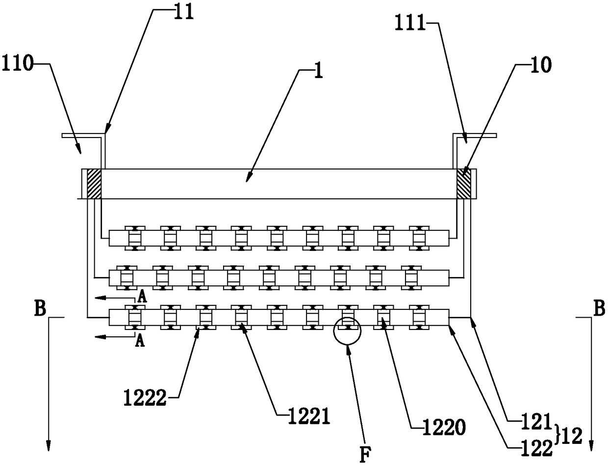
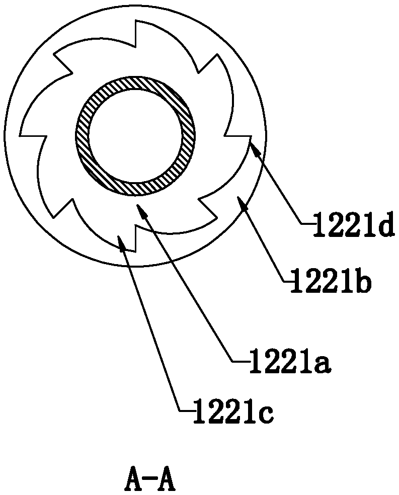
[0031] Such as Figure 1 to Figure 7 As shown, the present invention discloses a radiator for collecting waste heat energy of an air compressor. On the other side, the air collecting assembly 3 for receiving hot air, two rows of air inlets 10 arranged at intervals on the top of the heat dissipation main board 1, covering each row of air inlets 10 and having air inlets 110 and air outlets 111 respectively The converging frame 11 and the heat dissipation assembly 12 arranged at the bottom of the heat dissipation motherboard 1 and connected to each air intake hole 110; pipes 121, and between each corresponding first heat dissipation pipe 121, there is a heat dissipation module 122 in rotational communication. The outer wall of the heat dissipation module 122 is provided with several recesses 1220 at equal intervals in the axial direction, and in each recess 1220 passes through a one-way The rotating device 1221 axially rotates the connected heat dissipation air guide vane 1222, ...

Embodiment 2

[0040] A method for collecting waste heat energy of an air compressor, comprising the steps of:

[0041] S1: Pass the waste heat generated by the air compressor into the air intake hole set on the heat dissipation main board through the air inlet;

[0042]S2: The waste hot air entering the heat dissipation holes continues to pass through the heat dissipation components arranged between the heat dissipation holes, and the fan continues to dissipate the heat of the waste heat passing through the heat dissipation components and purify the internal heat;

[0043] S3: Collect and utilize the hot gas purified in S2 through the gas collection assembly;

[0044] S4: Exhaust the heat-dissipated waste heat in S2 through the air inlet provided at the air outlet of the heat-dissipating main board.

[0045] In a specific embodiment of the present invention, the hot waste gas discharged from S4 is used to keep the hot gas collected in S3 warm.

[0046] By adopting the above technical sche...


PUM


Abstract

The invention relates to a radiator for collecting waste heat energy of an air compressor and a collecting method thereof, and the radiator includes a heat dissipation main board, a heat dissipation fan arranged on one side of the heat dissipation main board, a gas collecting assembly arranged on the other side of the heat dissipation main board and used for receiving hot gas, two rows of air inlet holes spaced apart on the top of the heat dissipation main board, converging frames covering the rows of air inlet holes and each provided with an air inlet and an air outlet, and a heat dissipationassembly arranged on the bottom of the heat dissipation main board and connected with each air inlet hole. The heat dissipation assembly comprises first heat dissipation tubes communicating with theair inlet holes and being in one-to-one correspondence, and a heat dissipation module rotatably communicates with each corresponding first heat dissipation tube. The heat dissipation module is gradually inclined and spaced from one side close to the gas collection assembly to the other side in a stepped shape. The invention has the beneficial effects of recovering waste heat energy generated whenthe air compressor is working and applying the waste heat energy to industrial production and manufacturing, and improving the utilization rate of resources.

Description

technical field [0001] The invention relates to the technical field of heat dissipation collection equipment for waste heat of an air compressor, in particular to a radiator for collecting waste heat energy of an air compressor and a collection method thereof. Background technique [0002] Circuit board, also known as printed circuit board or printed circuit board, the English name is (Printed Circuit Board) PCB, (Flexible Printed Circuit board) FPC circuit board (FPC circuit board, also known as flexible circuit board, flexible circuit board is based on polyimide A highly reliable and excellent flexible printed circuit board made of polyester film or polyester film. It has the characteristics of high wiring density, light weight, thin thickness and good bendability. It is used in circuit board production In the process, it needs to be painted and the coating on the surface of the circuit board is dried in an oven to improve the performance of various aspects of the circuit ...

Claims


Application Information

Patent Timeline
IPC IPC(8): F04B39/06
CPCF04B39/06F04B39/066
Inventor 兰胜有
Owner QUZHOU CHUANTE ELECTRONICS TECH CO LTD
Why Eureka
Try Eureka