
Live-line insulator W-shaped pin electric pin remover

A live line and insulator technology, applied in the field of live line insulator W-type pin electric pin remover, can solve the problems of the influence of the pin removal operation, the W-type pin falling to the ground, and the lack of protection of the locking pin, so as to avoid insulator damage and operation Convenience, safety, and remarkable safety benefits

Active Publication Date: 2015-12-16
STATE GRID ZHEJIANG ELECTRIC POWER CO LTD JINHUA POWER SUPPLY CO +1
View PDF7 Cites 2 Cited by
  • Summary
  • Abstract
  • Description
  • Claims
  • Application Information

AI Technical Summary

Problems solved by technology

[0003] In the above work, the existing canceler has the following problems: (1) Due to the limitation of the structure of the insulator string, the operators on some towers cannot observe whether the canceler is in place, and the canceling operation is affected or even impossible. Operation; (2) The operator needs to keep a sufficient safe distance from the live wire, so the optional operating positions are limited, and it is difficult for the operator to operate the deactivator with a hand in some positions, and sometimes it requires the cooperation of multiple people, resulting in a waste of personnel; (3) At the same time, some The diameter of the insulator is large, and the operating rod is blocked when the pin remover is working, and the W-shaped pin cannot be knocked out smoothly, resulting in poor controllability and long working time; (4) The pin remover is prone to misoperation when hitting the W-shaped pin, which may accidentally injure the insulator; (5) There is no protection in the process of knocking out the locking pin, which may easily cause the W-shaped pin to fall to the ground, and there is a risk of injury from falling objects; etc. These technical problems need to be further resolved

Method used


Image

  • Live-line insulator W-shaped pin electric pin remover

Examples


Embodiment Construction

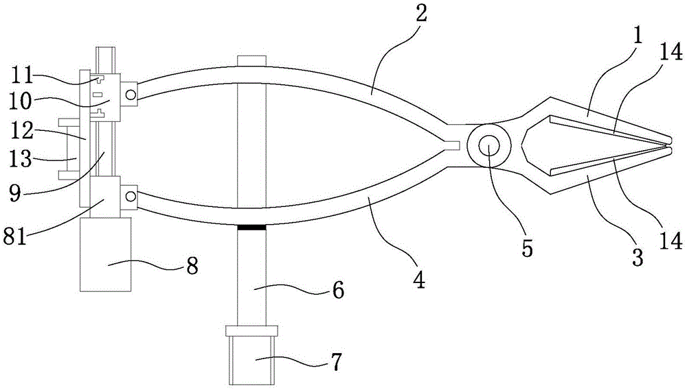
[0013] like figure 1 As shown, Embodiment 1 of a live line insulator W-type pin electric pin remover of the present invention includes an upper clip and a lower clip, and the upper clip and the lower clip are hinged by a rotating shaft 5, and the rotating shaft 5 is equipped with a spring, the upper clamp includes an upper clamp 1 and an upper clamp handle 2, the lower clamp includes a lower clamp 3 and a lower clamp handle 4, and the lower clamp 4 is connected to the insulating rod 6 through a connecting rod 6. The tops of the operating rods 7 are connected, and the inner sides of the upper chuck 1 and the lower chuck 3 are provided with anti-slip pads 14, which can prevent the W-shaped pin from slipping and causing it to be damaged or slip off and fall off.

[0014] The pin remover also includes an electric driving device, the electric driving device includes a motor 8, a screw 9 connected to the output end of the motor 8, and a nut 10 sleeved on the screw 9, and the end of ...


PUM


Abstract

The invention discloses a live-line insulator W-shaped pin electric pin remover, belonging to the power maintenance tool technology field and solving the problem that the prior art removes the pin through manual operation like beating up the W-shaped pin, which can mistakenly damage the insulator and is not easy to operate. The live-line insulator W-shaped pin electric pin remover comprises an upper clamping sheet and a lower clamping sheet; the upper sheet and the lower sheet are hinged together through a rotation shaft; the rotation shaft is provided with a spring; the upper sheet comprises an upper clamping head and an upper clamping handle; the lower clamping sheet comprises a lower clamping head and a lower clamping handle; the lower clamping handle is connected to a top of an insulation operation rod through a connection rod; the live-line insulator W-shaped pin electric pin remover also comprises an electric driving device comprising a motor, a screw rod connected to the output terminal of the motor and a nut sleeving the screw rod; the end of the lower clamping handle is fixed through a fixing block on the outer wall of the motor; and the end of the upper clamping handle is fixed on the nut.

Description

technical field [0001] The invention belongs to the technical field of electric power maintenance tools, and in particular relates to a W-shaped pin electric pin remover for live line insulators. Background technique [0002] After the transmission line runs for a long time, the insulators will be damaged by self-explosion, zero value, flashover, etc., and the insulators need to be replaced. Currently, the intermediate potential method is used to replace the hanging insulators of 35kV and above. The operator needs to fix the string of insulators to be removed first, and then use the pin remover to take out the locking pins between the insulators, disconnect the string of insulators to be removed, and finally successfully remove the string of insulators . At present, insulator locking pins used on transmission lines are mainly divided into W-type pins and R-type pins, among which W-type pins are most commonly used. When taking out the W-shaped pin, the operator looks for a ...

Claims


Application Information

Patent Timeline
Patent Type & Authority Applications(China)
IPC IPC(8): H02G1/02
Inventor 马永增缪寿成李炯赵俊杰方成戚惠明齐以涛蒋卫东郑宏伟顾浩
Owner STATE GRID ZHEJIANG ELECTRIC POWER CO LTD JINHUA POWER SUPPLY CO
Learn More