External rotor core, damping rotor and motor

An external rotor and iron core technology, applied to the static parts of the magnetic circuit, the shape/style/structure of the magnetic circuit, etc., can solve the problems of high manufacturing cost and maintenance cost, many slots and teeth, complex structure, etc., and achieve maintenance cost The effect of reducing, increasing continuity, and improving production efficiency

Active Publication Date: 2015-12-16
GREE ELECTRIC APPLIANCES INC +1
View PDF4 Cites 2 Cited by
  • Summary
  • Abstract
  • Description
  • Claims
  • Application Information

AI Technical Summary

Problems solved by technology

Correspondingly, the inner rotor core also needs punching sheets of two specifications, so a total of four sets of molds are required, and the manufacturing cost and maintenance cost are relatively high
In addition, there are many slots and teeth in the inner and outer rotor cores, and the structure is more complicated.

Method used


Image

  • External rotor core, damping rotor and motor
  • External rotor core, damping rotor and motor
  • External rotor core, damping rotor and motor

Examples


Embodiment Construction

[0031] The core of the present invention is to provide an outer rotor core to reduce manufacturing cost and maintenance cost;

[0032] Another core of the present invention is to provide a damping rotor and a motor.

[0033] Hereinafter, an embodiment will be described with reference to the drawings. In addition, the examples shown below do not limit the content of the invention described in the claims in any way. In addition, all the contents of the configurations shown in the following embodiments are not limited to be essential to the solutions of the invention described in the claims.

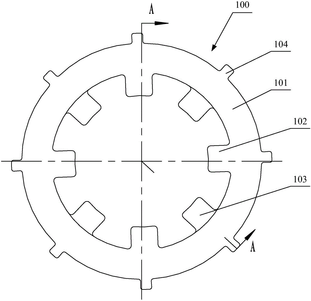
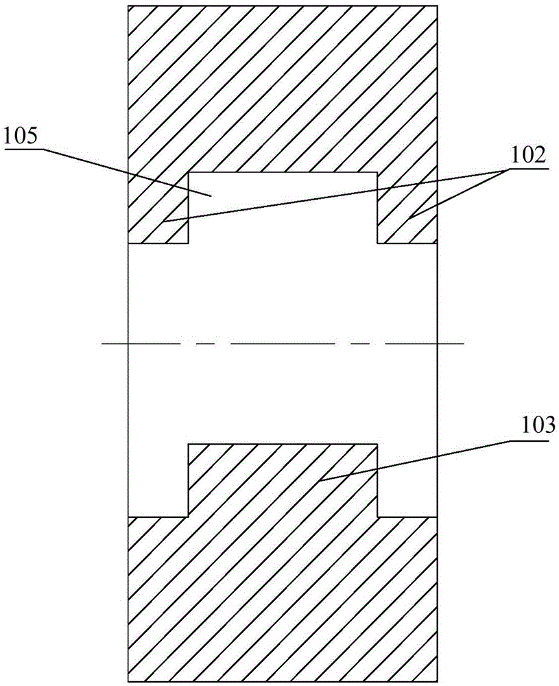
[0034] see figure 1 with figure 2 , figure 1 A top view of the outer rotor core provided by the embodiment of the present invention; figure 2 for figure 1 Sectional view along line A-A.

[0035] The outer rotor core 100 provided by the embodiment of the present invention sequentially includes a first end tooth segment, a middle slot segment and a second end tooth segment along the ...


PUM


Abstract

An embodiment of the invention discloses an external rotor core which sequentially comprises a first end part tooth segment, a central part groove segment and a second end part tooth segment in the axial direction. The external rotor core is formed by laminating a type of external rotor punching sheets. The external rotor punching sheet comprises a punching sheet body and a plurality of punching sheet teeth which are uniformly distributed on the inner wall of the punching sheet body. The punching sheet teeth, forming the first end part tooth segment and the second end part tooth segment by lamination, of the external rotor punching sheet are end surface inner teeth. The punching sheet teeth, forming the central part groove segment by lamination, of the external rotor punching sheet are central inner teeth. The center inner teeth and the end surface inner teeth are mutually staggered, so that positioning grooves are formed between the end surface inner teeth of the first end part tooth segment and the end surface inner teeth of the second end part surface tooth segment, and the positioning grooves are used for engaging with iron core outer teeth of an inner rotor iron core. The invention can reduce the manufacturing cost and the maintenance cost. The invention also discloses a damping rotor and a motor.

Description

technical field [0001] The invention relates to the technical field of motors, and more specifically relates to an outer rotor iron core, a damping rotor and a motor. Background technique [0002] The motor refers to an electromagnetic device that realizes the conversion or transmission of electric energy according to the law of electromagnetic induction. It is composed of a stator and a rotor. In order to better absorb vibration, the rotor is usually designed as a shock-absorbing rotor. [0003] The existing damping rotor includes two inner and outer rotor cores. The six teeth of the inner rotor core and the corresponding six grooves of the outer rotor core engage with each other and leave a certain gap. Rubber material is injected into the gap to reduce the vibration. The effect of shock. [0004] Both the outer rotor core and the inner rotor core are formed by lamination of punched sheets, and the outer rotor core is composed of three parts along the axial direction, whi...

Claims


Application Information

Patent Timeline
IPC IPC(8): H02K1/14
Inventor 杨光力文俊书王志强肖胜宇
Owner GREE ELECTRIC APPLIANCES INC
Why Eureka
Try Eureka