
Charging apparatus used with a mobile robot

a charging apparatus and mobile robot technology, applied in the direction of manufacturing tools, non-rotary current collectors, coupling device connections, etc., can solve the problems of failure to completely charge the rechargeable battery, affecting the charging effect, so as to improve the charging structure and reduce manufacturing costs. , the effect of preventing a charging failur

Inactive Publication Date: 2007-06-05
SAMSUNG ELECTRONICS CO LTD
View PDF4 Cites 105 Cited by
  • Summary
  • Abstract
  • Description
  • Claims
  • Application Information

AI Technical Summary

Benefits of technology

The present invention provides a charging apparatus for a mobile robot that has an improved charging structure. The charging apparatus includes a charging unit with a plurality of charging terminals that are brought into electrical contact with corresponding contact terminals on the mobile robot, allowing for efficient charging and preventing charging failures. The charging terminals may be arranged in rows and may include a support shaft and elastic member to restore the terminal to its original position. The charging apparatus may also include a coupling unit to connect the body and head of the charging terminal. The heads of the charging terminals may be bent in different directions when contacted by the mobile robot. The contact terminals may be disposed in a circular direction about the center of the mobile robot.

Problems solved by technology

When the mobile robot moves to be in contact with the charging unit, a position error may occur due to obstacles disposed on a support surface between the mobile robot and the charging unit, or friction between the wheels and the support surface.
Thus, it takes a long time to charge the mobile robot, and further there may occur a failure to incompletely charge the rechargeable battery.
The above method has a problem in that the trial and error is only reduced while the failure of an electrical connection (contact) occurs frequently because the mobile robot approximately detects the electrical contact position.
Therefore, the above conventional method is not practical.
However, this conventional method of using the guide unit also has a problem in that it is uneconomical because the guide unit is expensive.

Method used


Image

  • Charging apparatus used with a mobile robot
  • Charging apparatus used with a mobile robot
  • Charging apparatus used with a mobile robot

Examples


Embodiment Construction

[0034]Reference will now be made in detail to the preferred embodiments of the present invention, examples of which are illustrated in the accompanying drawings, wherein like reference numerals refer to like elements throughout. The embodiments are described below in order to explain the present invention by referring to the figures.

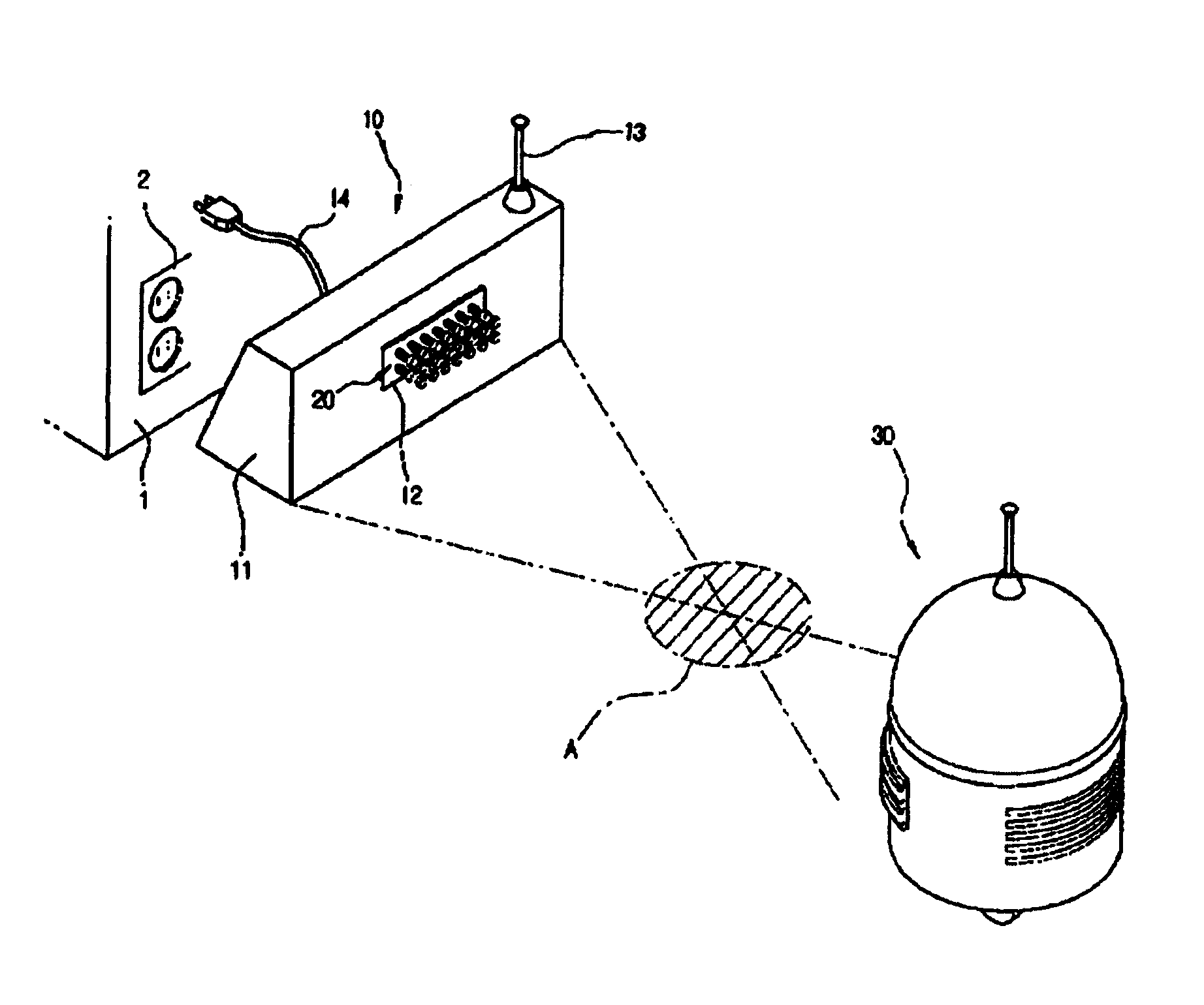
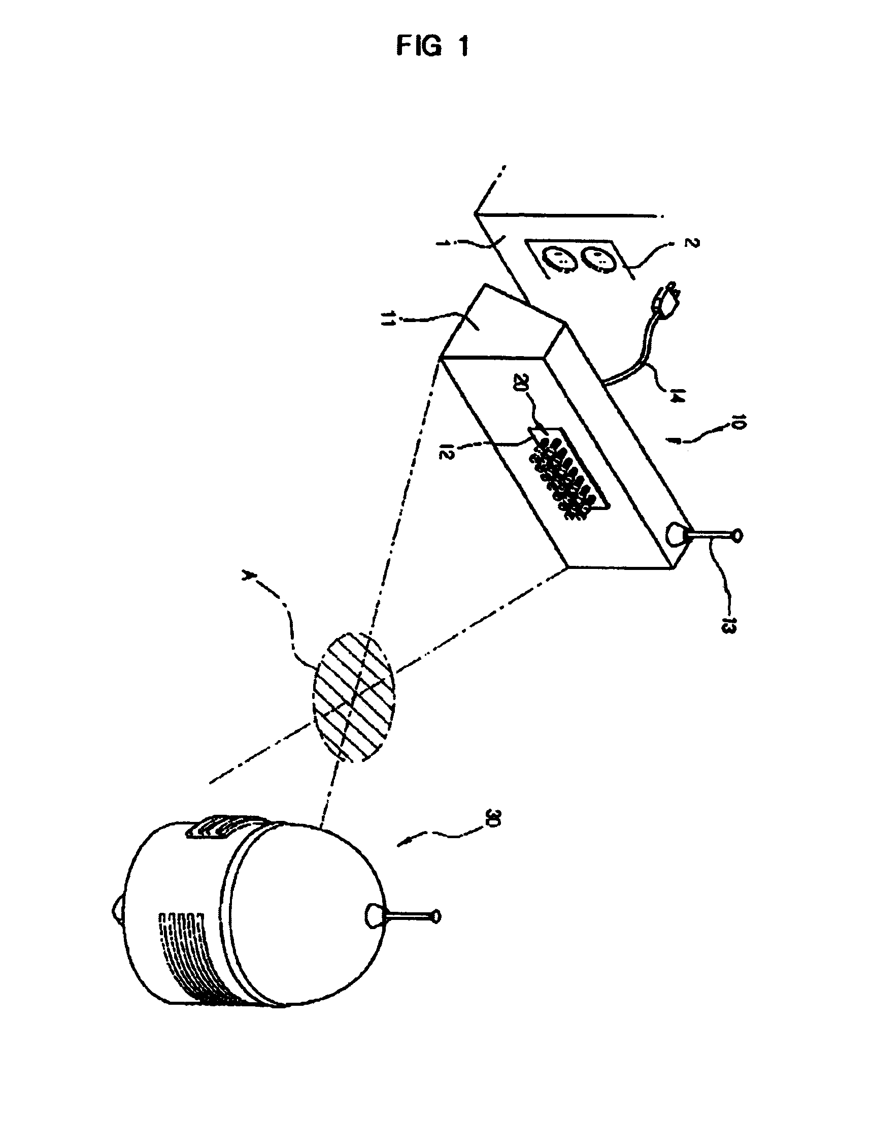
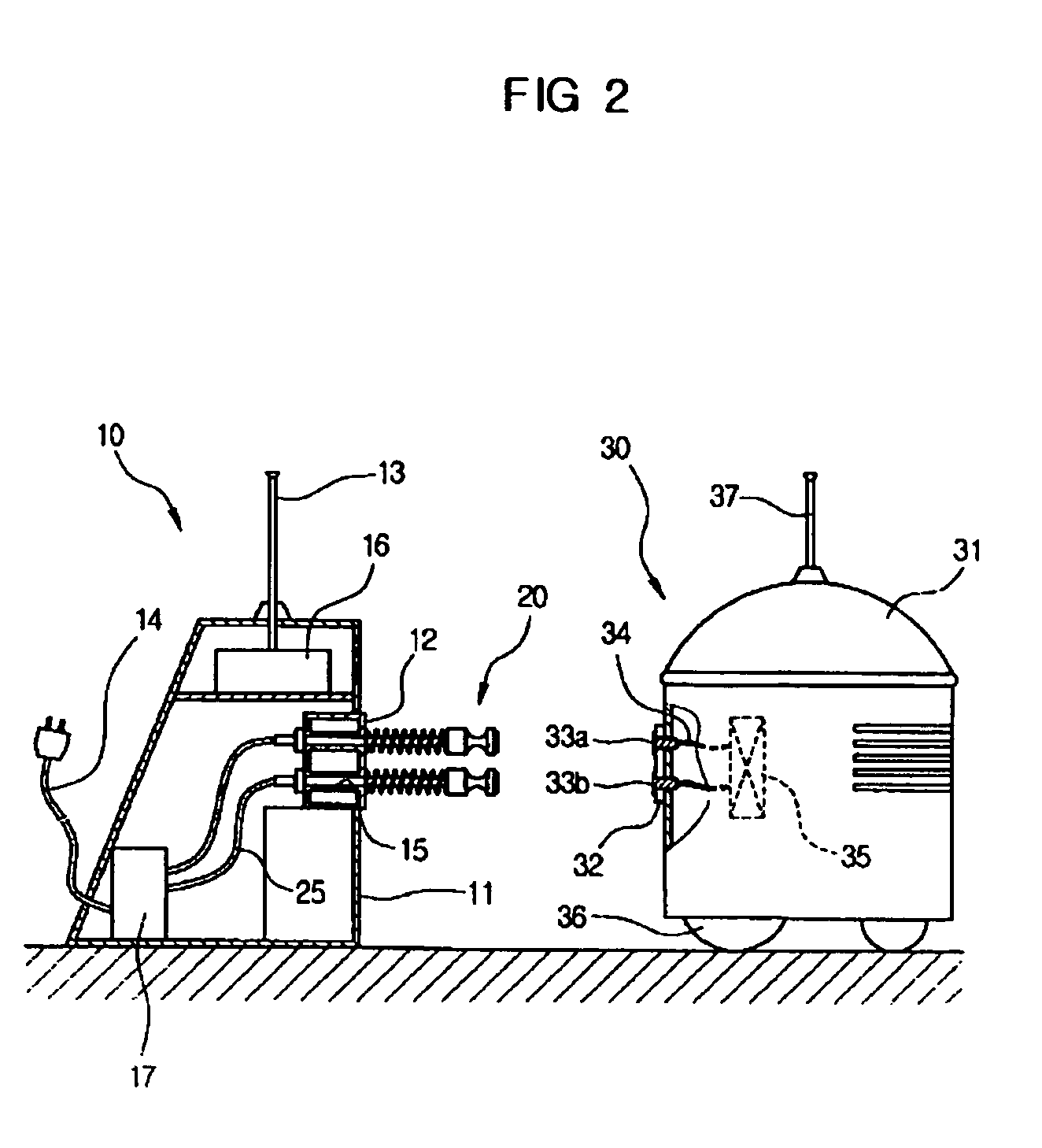
[0035]FIG. 1 is a perspective view of a charging apparatus used with a mobile robot 30 according to an embodiment of the present invention. FIG. 2 is a view showing the mobile robot 30 which approaches a charging unit 10 included in the charging apparatus of FIG. 1.

[0036]As shown in FIG. 1, the charging apparatus used with the mobile robot 30 according to the present invention includes the charging unit 10 and the mobile robot 30.

[0037]The charging unit 10 includes a casing 11, a first terminal mounting board 12 provided on an outer surface of the casing 11, and a plurality of charging terminals 20 mounted thereon. A first antenna 13 is provided on an up...


PUM


Abstract

A charging apparatus used with a mobile robot has an improved charging structure so that a mobile robot is easily brought into electrical contact with a charging unit, thereby reducing manufacturing costs and preventing a charging failure. The charging unit is provided with a plurality of charging terminals which are brought into electrical contact with corresponding ones of contact terminals of the mobile robot. Each of the charging terminals includes a body and a head. A contact plate is mounted to a predetermined portion of the head to be brought into electrical contact with a corresponding one of the contact terminals.

Description

CROSS-REFERENCE TO RELATED APPLICATIONS[0001]This application claims the benefit of Korean Patent Application No. 2003-73327, filed Oct. 21, 2003 in the Korean Intellectual Property Office, the disclosures of which are incorporated herein by reference.BACKGROUND OF THE INVENTION[0002]1. Field of the Invention[0003]The present invention relates to a charging apparatus used with a mobile robot and, more particularly, to a charging apparatus used with a mobile robot to recharge the mobile robot.[0004]2. Description of the Related Art[0005]Generally, mobile robots have been used in various industrial fields to maneuver elements or working tools, which are required to manufacture products, to desired positions.[0006]Recently, there is a growing tendency to increase use of the mobile robots at home as well as in the industrial fields. At home, the mobile robot is used to clean a room, guard a user against attack, and protect the user's property.[0007]The mobile robot is designed to fulfil...

Claims


Application Information

Patent Timeline
Patent Type & Authority Patents(United States)
IPC IPC(8): H02J7/00H01R13/24H01R13/64A47L9/00B25J5/00B25J19/00G05D1/02H01R13/631H01R41/00H01R43/26
CPCA47L9/00B25J19/005H01R13/2421H01R13/6315H01R43/26H02J7/0042B60L11/1818B60L11/1825B60L11/1833B25J5/00Y02T90/128A47L2201/022B60L2260/32Y02T10/7005Y02T90/125Y02T90/121Y02T90/14B60L53/16B60L53/31B60L53/36Y02T10/70Y02T10/7072Y02T90/12H02J7/02
Inventor YANG, SOO-SANGLEE, YOUN-BAEKOH, YEON-TAEKLEE, JA-WOO
Owner SAMSUNG ELECTRONICS CO LTD
Learn More