Organic light emitting display

a technology of light-emitting display and organic material, which is applied in the direction of instruments, computing, electric digital data processing, etc., can solve the problems of increased manufacturing cost and increased manufacturing cost, and achieve the effect of reducing manufacturing cost and uniform brightness

Active Publication Date: 2006-04-06
SAMSUNG DISPLAY CO LTD
View PDF10 Cites 114 Cited by
  • Summary
  • Abstract
  • Description
  • Claims
  • Application Information

AI Technical Summary

Benefits of technology

[0011] In one embodiment, the present invention provides a demultiplexer, an organic light emitting display using the sam

Problems solved by technology

This causes an increase in manufacturing cost.
In particular, as the resolution and size of the image display portion 30

Method used


Image

  • Organic light emitting display
  • Organic light emitting display
  • Organic light emitting display

Examples


Embodiment Construction

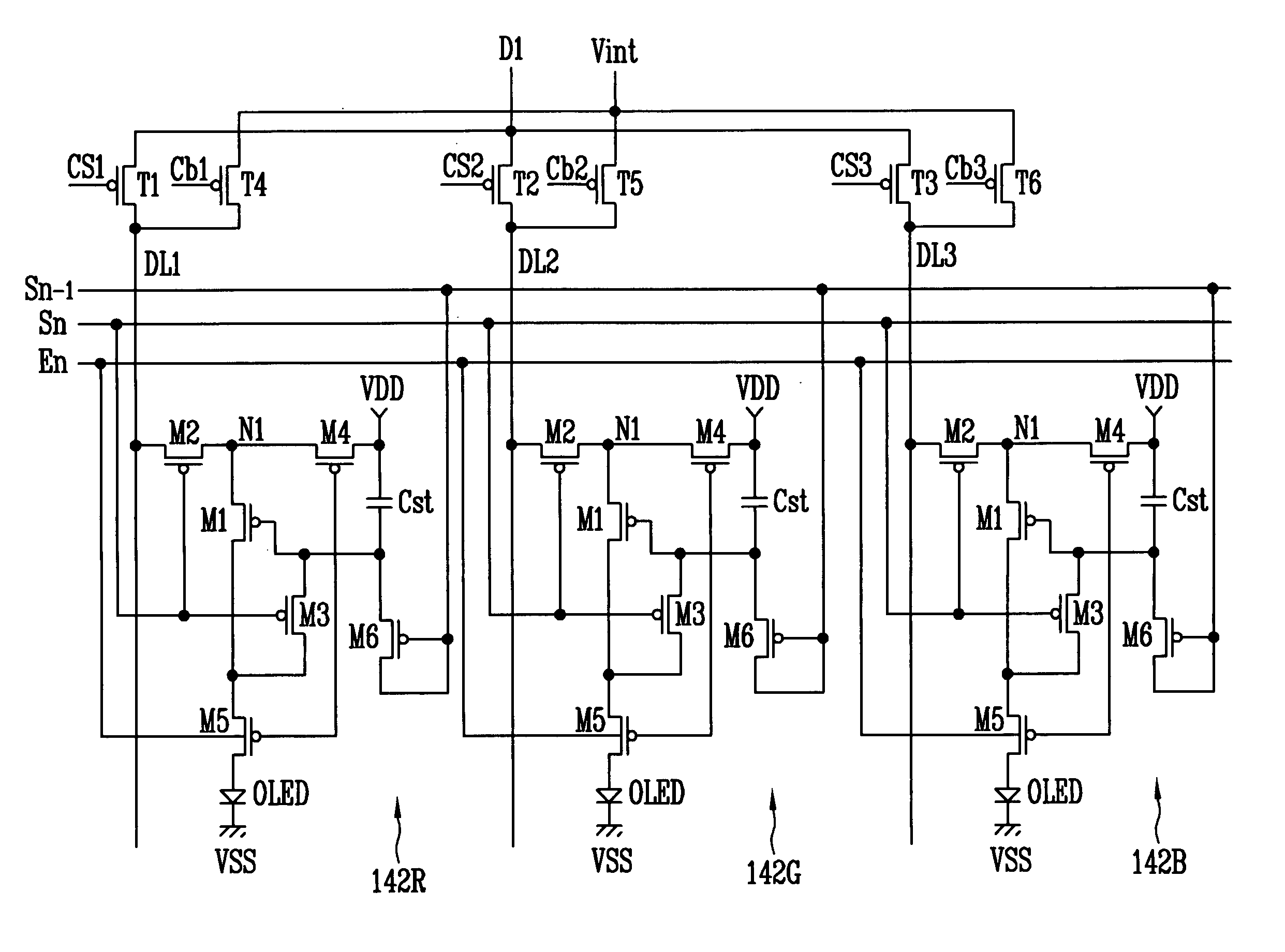
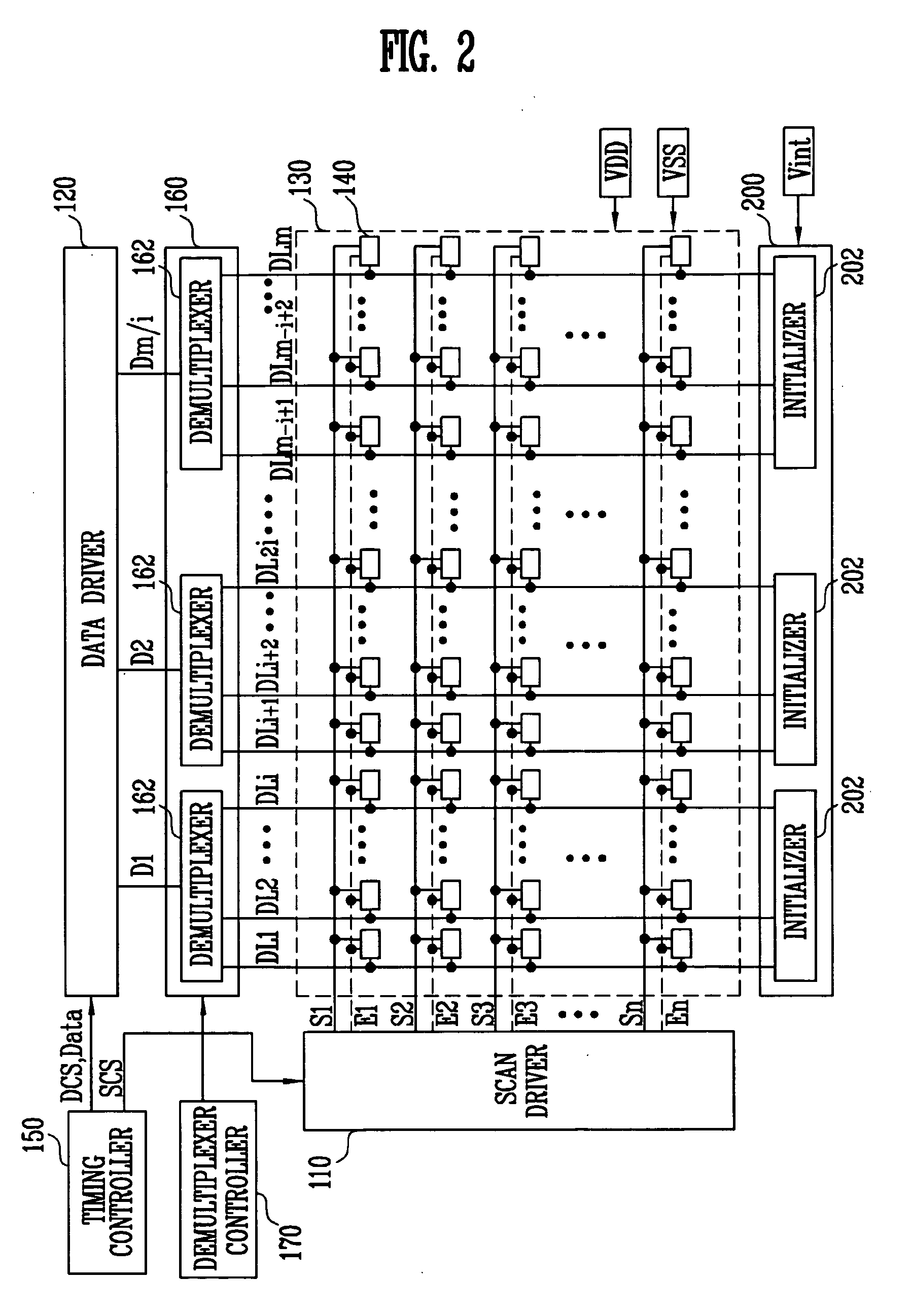
[0033]FIG. 2 is a diagram showing an organic light emitting display according to an embodiment of the present invention. Referring to FIG. 2, the organic light emitting display includes a scan driver 110, a data driver 120, an image display portion 130, a timing controller 150, a demultiplexer block 160, a demultiplexer controller 170, and an initialization block 200.

[0034] The image display portion 130 includes a plurality of pixels 140 arranged at regions intersected by scan lines S1 to Sn and second data lines DL1 to DLm. Each of the pixels 140 emits light corresponding to a data signal supplied from a respective second data line DL.

[0035] The scan driver 110 generates scan signals in response to scanning drive control signals SCS supplied from the timing controller 150, and sequentially supplies the generated scan signals to the scan lines S1 to Sn. In addition, the scan driver 110 generates light emitting control signals in response to the scanning drive control signals SCS, ...


PUM


Abstract

An organic light emitting display capable of reducing the manufacturing cost and displaying images with uniform brightness. The organic light emitting display includes: a data driver for supplying a plurality of data signals to a plurality of first data lines, respectively; an image display portion having a plurality of second data lines, a plurality of scan lines, and a plurality of pixels; and a demultiplexer having a plurality of data transistors arranged in the respective first data lines to supply the plurality of data signals supplied to the first data lines to the plurality of second data lines, and a plurality of capacitors connected between respective gate terminals of the plurality of data transistors and the second data lines.

Description

CROSS-REFERENCE TO RELATED APPLICATIONS [0001] This application claims the priority of Korean Patent Application No. 2004-75821, filed on Sep. 22, 2004, in the Korean Intellectual Property Office, the entire disclosure of which is incorporated herein by reference. FIELD OF THE INVENTION [0002] The present invention relates to an organic light emitting display and a driving method thereof and, more specifically, to a demultiplexer, an organic light emitting display using the same, and a driving method thereof, capable of reducing the manufacturing cost and displaying images with uniform brightness. BACKGROUND [0003] Recently, various flat panel displays have been developed to compensate for weight and volume drawbacks of a cathode ray tube. There are different types of flat panel displays, such as liquid crystal displays, field emission displays, plasma display panels, and organic light emitting displays. [0004] Among these flat panel displays, an organic light emitting display can e...

Claims


Application Information

Patent Timeline
IPC IPC(8): G09G3/30
CPCG09G3/3233G09G3/3291G09G2300/0452G09G2300/0819G09G2300/0842G09G2300/0861G09G2310/0235G09G2310/0297G09G2320/043Y10S370/916G09G3/30
Inventor KIM, YANG WAN
Owner SAMSUNG DISPLAY CO LTD
Why Eureka
Try Eureka