[0044] The technical solutions in the embodiments of the present invention will be clearly and completely described below in conjunction with the accompanying drawings in the embodiments of the present invention. Obviously, the described embodiments are only a part of the embodiments of the present invention, rather than all the embodiments. Based on the embodiments of the present invention, all other embodiments obtained by those of ordinary skill in the art without creative work shall fall within the protection scope of the present invention.
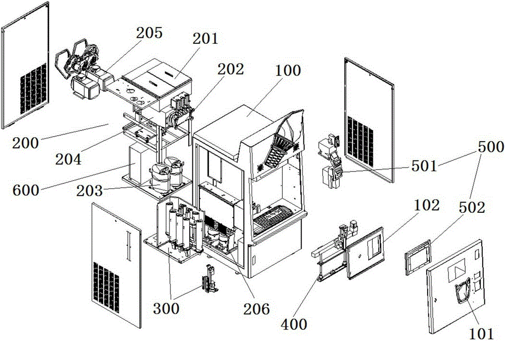
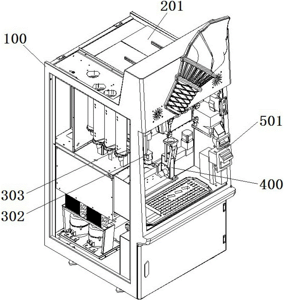
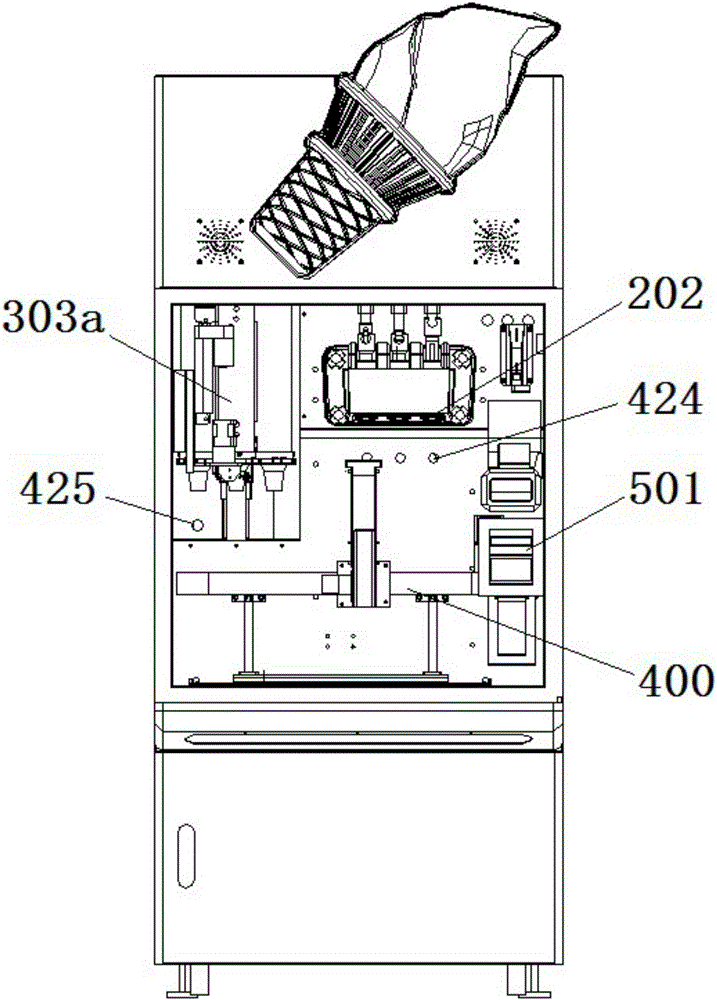
[0045] Such as Figure 1 to Figure 11 As shown, an embodiment of the present invention is an ice cream vending machine, which includes a body 100 with a delivery port 101, an ice cream making unit 200 loaded on the body 100, a cup supply unit 300, and a receiving material. The delivery unit 400, the operation unit 500, and the control unit 600; the receiving and delivery unit 400 is arranged between the ice cream making unit 200 and the cup supply unit 300; the ice cream making unit 200, the cup supply unit 300 , The receiving and shipping unit 400 and the operating unit 500 are respectively connected to the control unit 600; wherein, the shipping port 101 is provided with an electric door and window 102.
[0046] The ice cream making unit 200 includes a material tank 201, a frosting stirring mechanism, and a discharge port 202 for outputting ice cream; the frosting stirring mechanism includes a stirring device that is connected to the material tank 201 and is equipped with a refrigeration system 203 The cylinder 204 and the agitator 205 rotatably inserted in the mixing cylinder 204; the discharge port 202 communicates with the mixing cylinder 204 and is provided with a valve; the refrigeration system 203, the agitator 205 and the valve It is controlled and driven by the control unit 600 to make and extrude ice cream.
[0047] The cup tube supply unit 300 includes a rotating mechanism 301, a cup tube clamping mechanism 302, and a plurality of cup tube placement tubes 303; the rotating mechanism 301 and the cup tube clamping mechanism 302 are installed in the body 100, and the cup tube The placement tube 303 is installed on the movement track of the rotation mechanism 301; the rotation mechanism 301 is controlled and driven by the control unit 600 to rotate the cup tube placement tube 303 to move the target cup tube placement tube 303a to the cup tube The position of the clamping mechanism 302; the cup clamping mechanism 302 is driven by the control unit 600 to remove the cup from the cup placement tube 303 and put it into the receiving and shipping unit 400. It can be seen that the present invention adopts the method of rotating the transplanting cup tube placement tube 303 to store the cup tube, which is conducive to automatic selection and provides a variety of different types of cup tube, greatly increasing the supply quantity and storage space of the cup tube, and ensuring ice cream Normal and stable supply of vending machines.
[0048] The material receiving and shipping unit 400 includes a lifting bracket mechanism 401, a horizontal conveying mechanism 402, and a material receiving and shipping mechanism 403; the lifting bracket mechanism 401 is installed in the body 100; the horizontal conveying mechanism 402 is installed in the The lifting bracket mechanism 401 is driven by the lifting bracket mechanism 401 to move up and down; the material receiving and shipping mechanism 403 is installed on the horizontal conveying mechanism 402 and driven by the horizontal conveying mechanism 402 to move left and right; the lifting bracket The mechanism 401, the horizontal conveying mechanism 402, and the material receiving and delivering mechanism 403 are driven by the control unit 600 to move to the cup tube supply unit 300 to receive the cup tube, and transfer the cup tube to the ice cream making unit 200 Ice cream, and the cup tube receiving the ice cream is extended to the delivery port 101; wherein, when receiving the material, the receiving and shipping mechanism 403 can place the cup tube vertically below the discharge port 202, , The material receiving and shipping mechanism 403 can place the cup cylinder obliquely toward the inside of the machine body 100 and extend to the shipping port 101. It can be seen that by simulating manual operation, the present invention enables the vending machine to automatically transfer the cup and tube to receive ice cream, and move the container down during the ice cream loading period, so that the ice cream is stacked on the cup tube layer by layer in a preset shape, which can achieve full The purpose of automatic ice cream vending is to save labor costs, and ice cream can be sold without anyone in various announcement places around the clock. At the same time, because the receiving and shipping mechanism 403 can vertically place the cup tube under the discharge opening 202 when receiving the material, it can ensure that the ice cream is in a good shape on the cup tube; when shipping, the receiving and shipping mechanism 403 can The cup tube is placed obliquely toward the inside of the body 100 of the ice cream vending machine and extends to the delivery port 101, so as to prevent the hand from directly touching the ice cream due to an improper taking angle, which is convenient for consumers or sellers to take.
[0049] The operating unit 500 includes a charging device 501 for receiving coins, banknotes, and chip cards, and an operation panel 502 that is open to people for selective operation. The charging device 501 and the operation panel 502 are installed outside the body 100. Manually operate to control the control unit 600. After the consumer completes the charging procedure through the charging device 501, he can input a command through the operation panel 502 to control the control unit 600 to select the ice cream flavor and cup type, which can provide more choices for consumers' preferences in a freely collocation and combination manner, and The process of purchasing and selling is fully automated, and the operation is convenient and simple.
[0050] The lifting support mechanism 401 includes a first push rod 404, a fixed support 405, a movable support 406 and two vertical guide posts 407; the body of the first push rod 404 is rotatably connected with the body 100, and the The power output end of a push rod 404 is rotatably connected with the movable bracket 406; the fixed bracket 405 and the movable bracket 406 are arranged in parallel up and down; the fixed bracket 405 is fixed on the body 100; Under the action of the push rod 404, the movable bracket 406 can be close to or away from the fixed bracket 405; the lower ends of the two vertical guide posts 407 are connected to the movable bracket 406, and the upper ends movably pass through the fixed bracket 405. The bracket 405 extends and extends; the horizontal conveying mechanism 402 is fixed on the upper ends of the two vertical guide posts 407. Wherein, the first push rod 404 may preferably be an electronic push rod. When the first push rod 404 extends, under the guiding action of the vertical guide post 407 and the fixed support 405, the movable support 406 is pushed to move vertically down, and at the same time the entire horizontal conveying mechanism 402 is driven to move down vertically; on the contrary, When the first push rod 404 is retracted, under the guiding action of the vertical guide post 407 and the fixed support 405, the movable support 406 is pushed to move up vertically, and at the same time the entire horizontal conveying mechanism 402 is driven to move up vertically. In this way, the vertical transfer of the cup tube is realized.
[0051] The horizontal conveying mechanism 402 includes a first motor 408, a guide rail 409, and a moving seat 410. The guide rail 409 is laterally fixed between the upper ends of the two vertical guide posts 407, and the moving seat 410 is installed on the guide rail. 409 and driven by the first motor 408 to move along the guide rail 409; the material receiving and delivering mechanism 403 is fixed on the moving base 410. Wherein, the first motor 408 may preferably be a stepping motor, and cooperate with the timing belt sliding module to move the moving base 410 along the guide rail 409, that is, drive the entire receiving and shipping mechanism 403 to move on the lateral guide rail 409. Thus, the transfer of the cup tube in the left-right direction is realized. Of course, the first motor 408 can also be replaced by an electronic push rod, and the electronic push rod can directly act on the movable base 410.
[0052] The receiving and shipping mechanism 403 includes a base 411, a second motor 412, an eccentric rod 413, a connecting rod 414, a rocker rod 415, a first swing rod 416, a second swing rod 417, a first mandrel 418, and a Two mandrels 419 and a cup holder 420; the base 411 is fixed on the movable base 410, the body of the second motor 412 is fixed on the base 411 through a mounting plate, and its power output end passes through the mounting The plate is fixedly connected to one end of the eccentric rod 413, the other end of the eccentric rod 413 is rotatably connected to one end of the connecting rod 414, and the other end of the connecting rod 414 is rotatably connected to one end of the rocker lever 415. Rotational connection, the other end of the rocker lever 415 is fixedly connected to the first mandrel 418, the axial ends of the first mandrel 418 are respectively rotatably connected to the base 411, the first One end of the swing rod 416 is fixedly connected to the axial end of the first spindle 418, and the other end of the first swing rod 416 is rotatably connected with the first fulcrum of the cup holder 420; the second core Both ends of the shaft 419 in the axial direction are respectively rotatably connected with the base 411, one end of the second swing rod 417 is fixedly connected with the axial end of the second mandrel 419, and the second swing rod 417 The other end is rotatably connected with the second fulcrum of the cup holder 420; the material receiving and shipping mechanism 403 further includes a first induction switch 421, a second induction switch 422 and an induction head 423, and the induction head 423 is arranged at The power output end of the second motor 412 rotates in the radial direction and with the rotation of the power output end of the second motor 412; the first induction switch 421 and the second induction switch 422 are shipped according to the material receiving The receiving and shipping positions of the mechanism 403 are respectively set on the movement track corresponding to the sensing head 423. Wherein, the second motor 412 may preferably be a geared motor. When the power output end of the second motor 412 drives the induction head 423 to the first induction switch 421, the first induction switch 421 sends a stop signal to the second motor 412. At this time, the material receiving and shipping mechanism 403 is in the vertical feeding state ,Such as Figure 8 As shown; when the rotation shaft of the second motor 412 drives the induction head 423 to reverse to the second induction switch 422, the second induction switch 422 sends a stop signal to the second motor 412, at this time, the material receiving and shipping mechanism 403 is in an inclined extension Shipment status, such as Figure 7 Shown. Thus, accurate control of the receiving and shipping positions of the receiving and shipping mechanism 403 is realized.
[0053] The rotating mechanism 301 includes a third motor 304, an active transmission mechanism 305, a driven transmission mechanism 306 and a timing belt 307, and the power output end of the third motor 304 is fixedly connected to the power input end of the active transmission mechanism 305; The timing belt 307 is rotatably connected between the driving transmission mechanism 305 and the driven transmission mechanism 306; the cup tube placement tube 303 is evenly installed on the timing belt 307 along the rotation track of the timing belt 307 on. When the cup tube in the cup tube 303 is used up, under the control of the control unit 600, the third motor 304 is driven to drive the cup tube 303 to rotate, so that the cup tube 303 with the cup tube moves to empty. The position of the cup tube where the tube 303 is placed on the cup tube instead of the empty cup tube tube 303 is used to continue the supply of the cup tube, so as to achieve the purpose of automatic switching and circulating supply of the cup tube.
[0054] The cup-clamping mechanism 302 includes a second push rod 308, a sliding rail 309, a sliding block 310, and a cup-taking clamping jaw 311; the body of the second push rod 308 and the sliding rail 309 are fixed on the body 100, The sliding block 310 is slidably mounted on the sliding rail 309, and the power output end of the second push rod 308 is fixedly connected to the sliding block 310; the cup-taking clamping jaw 311 includes two claw arms 313 formed a claw 312 and a fourth motor 314; the body of the fourth motor 314 is mounted on the slider 310 through a connecting plate, and its power output end is connected to the two claw arms 313 through a gear transmission mechanism. When working, the second push rod 308 pushes the sliding block 310 to drive the cup-clamping jaw 311 to move on the sliding rail 309, so that the claw mouth 312 extends to the cup position at the bottom of the target cup tube 303a, and then controls the fourth motor 314 Rotate to make the two claw arms 313 move toward or away from each other to realize the clamping and releasing actions, and the cups can be taken and placed in a simple and fast manner. In addition, for the size of the claw opening 312 formed between the two claw arms 313 of the cup taking clamping jaw 311, the size of the claw opening 312 can be adjusted by controlling the rotation angle of the fourth motor 314, which is simple, convenient and highly versatile. . The fourth motor 314 can be a stepping motor, of course, other motors with adjustable rotation angle are also applicable.
[0055] In order to precisely control the soft and hard taste of ice cream, the inner wall of the mixing tank 204 is equipped with a temperature sensor for detecting the temperature of the ice cream in the mixing tank 204. The temperature sensor is connected to the control unit 600. The temperature sensor The controller sends a detection signal to the control unit 600 to control the refrigeration temperature of the refrigeration system 203.
[0056] In order to achieve precise control of the position of the target cup tube placement tube 303a, an encoding sensor for detecting the position of the target cup tube placement tube 303a is installed on the outside of the cup tube placement tube 303, and the encoding sensor is connected to the control unit 600, It includes an induction switch 315 and a number of induction heads 316, the induction heads 316 are respectively installed on each of the cup tube placement tubes 303 and correspond to the induction switches 315 one by one when rotating with the rotating mechanism 301; When the sensor switch 315 detects that it is not the sensor head 316 on the target cup tube 303a, the code sensor sends a detection signal to the control unit 600 to activate the rotating mechanism 301 to place the next cup tube into the tube. The sensor head 316 on the 303 moves to a position corresponding to the sensor switch 315 for the next detection, until the sensor switch 315 detects the sensor head 316 on the target cup tube 303a, the encoder sensor The detection signal is sent to the control unit 600 to stop the rotation mechanism 301. The code sensor is preferably a magnetoelectric sensor.
[0057] In order to ensure the continuous use of the vending machine, the remaining cups need to be detected and alarmed to remind the replenishment. Therefore, under the cup placement tube 303 is installed a first for detecting the storage status of the cups in the cup placement tube 303. The material sensor 317, the first material sensor 317 is connected to the operation panel 502, the first material sensor 317 sends a detection signal to the operation panel 502 to prompt the cup tube to place the cup in the tube 303 The storage status of the cartridge. The first material sensor 317 is preferably a photoelectric sensor.
[0058] In order to achieve precise control of the position of the cup tube receiving ice cream, a second material sensor 424 for detecting whether the cup tube is moved to a position below the discharge opening 202 is installed below the discharge port 202. The second material sensor The second material sensor 424 is connected to the control unit 600. When the second material sensor 424 detects that the cup is moved to a position below the discharge port 202, the second material sensor 424 sends a detection signal to the The control unit 600 thus stops the material receiving and shipping unit 400 and opens the valve of the discharge port 202; when the second material sensor 424 detects that the cup cylinder has not moved to a position below the discharge port 202 At this time, the second material sensor 424 sends a detection signal to the control unit 600 to close the valve of the discharge port 202, and drives the receiving and shipping unit 400 to move the cup to the discharge The position below the mouth 202. The second material sensor 424 is preferably a photoelectric sensor.
[0059] In order to achieve precise control of the position of the receiving and shipping mechanism 403 for receiving the cup, a second device for detecting whether the receiving and shipping mechanism 403 has been moved to the position below the target cup placement tube 303a is installed under the cup placement tube 303. A three-material sensor 425, the third material sensor 425 is connected to the control unit 600, when the third material sensor 425 detects that the material receiving and shipping mechanism 403 is moved to the target cup tube placement tube 303a In the lower position, the third material sensor 425 sends a detection signal to the control unit 600 to drive the cup-cylinder clamping mechanism 302 to remove the cup from the target cup-tube placement tube 303a and put it into the receiving Material delivery mechanism 403; when the third material sensor 425 detects that the material receiving and delivering mechanism 403 has not been moved to the position below the target cup tube placement tube 303a, the third material sensor 425 will detect It is sent to the control unit 600 to drive the lifting bracket mechanism 401 and the horizontal conveying mechanism 402 to move the material receiving and shipping mechanism 403 to a position below the target cup tube placement tube 303a. The third material sensor 425 is preferably a photoelectric sensor.
[0060] In order to ensure the continuous use of the vending machine, it is necessary to detect and alarm the remaining raw materials to remind the replenishment. Therefore, a fourth material sensor for detecting the storage status of the raw materials in the material tank 201 is installed in the material tank 201. The fourth material sensor is connected to the operation panel 502, and the fourth material sensor sends a detection signal to the operation panel 502 to prompt the storage state of the raw material in the material cylinder 201. The fourth material sensor is preferably a liquid level sensor.
[0061] The operation panel 502 is provided with a wireless transceiving device that is open to consumers for Internet payment and orders. The operation panel 502 can be a touch screen display or a tablet computer, and can also be used to play advertisements when it is idle, with various functions.
[0062] Considering that ice cream may generally include flavors such as vanilla and chocolate, and a combination of the two, the material tank 201 is provided with more than two, the frosting and stirring mechanism is provided with more than two, and the discharge port 202 is provided with three More than one.
[0063] The material cylinder 201 is equipped with a material cylinder refrigeration system 206. In the standby mode, the raw material in the cylinder 201 can be pre-frozen through the cylinder refrigeration system 206, and at the same time it has the effect of heat preservation. The refrigeration system 203 and the agitator 205 in the frosting stirring mechanism are activated for rapid freezing after the order is generated. And mixing and extruding, more energy-saving and efficient.
[0064] The above-disclosed are only preferred embodiments of the present invention. Of course, the scope of rights of the present invention cannot be limited by this. Therefore, equivalent changes made in accordance with the scope of the patent application of the present invention still fall within the scope of the present invention.