In-shaft spline and outer circle coaxiality machining and positioning device and process method

A positioning device and internal spline technology, applied in the field of mechanical processing, can solve the problems of reducing processing accuracy, affecting tool rigidity, cumbersome operation, etc., and achieve the effect of improving coaxiality processing accuracy, improving processing accuracy, and simple operation

Inactive Publication Date: 2015-12-23
CHINA COAL ZHANGJIAKOU COAL MINING MACHINERY
View PDF6 Cites 4 Cited by
  • Summary
  • Abstract
  • Description
  • Claims
  • Application Information

AI Technical Summary

Problems solved by technology

The reason is that the center after grinding the hole is not the same as the center of the matching block, drilling the center hole, turning the outer circle, and grinding the outer circle, so the coaxiality between the inner spline and the outer circle cannot be guaranteed.
The original clamping method uses a three-jaw chuck to clamp the outer circle of the workpiece, and then presses the end face with a pressure plate. However, the outer circle and shaft length of the workpiece are different, and some workpieces cannot be directly clamped. Only multiple washers can be configured to position them in a suitable position. , the operation is cumbersome, the positioning is unstable, and it is difficult to find the alignment
As a result, the positioning datum of the workpiece and the alignment datum cannot be unified, and the long axial dimension affects the rigidity of the tool and reduces the machining accuracy
The traditional processing technology and clamping method not only make the positioning reference and alignment reference not always consistent when machining the inner spline, but also the positioning is unstable, and the clamping and alignment are unreasonable, resulting in the inability to guarantee the coaxiality of the inner spline and the outer circle It affects the processing accuracy of the product, and the most important thing is to shorten the service life of the product
This processing method is far from meeting the current high-quality product design requirements

Method used


Image

  • In-shaft spline and outer circle coaxiality machining and positioning device and process method
  • In-shaft spline and outer circle coaxiality machining and positioning device and process method

Examples


Embodiment Construction

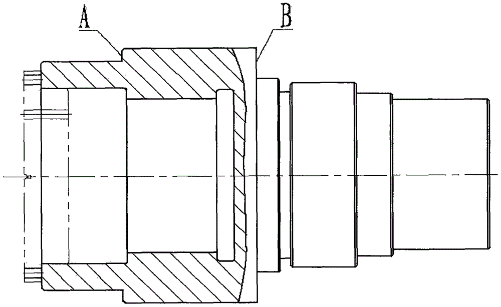
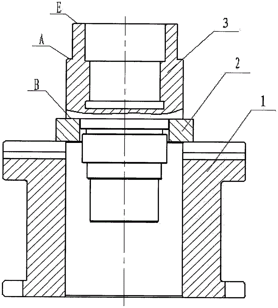
[0020] Depend on Figure 1~2 It can be seen that

[0021] Design and manufacture a positioning device with stable positioning and convenient operation. The device solves the problems of unstable positioning, non-uniform benchmarks and insufficient rigidity of the machine tool spindle when machining internal splines, improves machining accuracy, and makes clamping and alignment more reasonable. The device consists of a carcass and a gasket.

[0022] Change the process of grinding the spline hole to process after grinding the outer circle, and when grinding the outer circle, the relevant end face must be ground, so that when grinding the spline hole, the ground outer circle and the ground end face can be aligned to ensure the spline The hole has the same center as the outer circle. The processing steps to ensure the coaxiality of the inner spline and the outer circle are as follows:

[0023] Follow the steps below to complete the machining of the coaxiality of the spline in ...


PUM


Abstract

The invention discloses an in-shaft spline and outer circle coaxiality machining and positioning device and a process method. According to a traditional method, the outer circles of workpieces are clamped through a chuck, and then the end faces are pressed; due to the fact that the sizes of the outer circles and the axial lengths of the workpieces are different, some workpieces can not be directly clamped and can not be positioned until multiple gaskets are arranged at appropriate positions, positioning standards and alignment standards of the workpieces can not be unified, the tool rigidity is influenced when the axial sizes are large, and the machining accuracy is low. The in-shaft spline and outer circle coaxiality machining and positioning device is composed of a jig body and a gasket. Four U-shaped grooves which are evenly distributed are formed in the bottom of the jig body. The jig body is fixed to a working table when T-shaped bolts penetrate the U-shaped grooves. Four T-shaped grooves which are evenly distributed are formed in the upper end of the jig body. Workpieces are fixed when T-shaped bolts penetrate the T-shaped grooves. The gasket is placed on the jig body, and it must be ensured that two planes are parallel. The workpieces are placed on the gasket. The gasket is selected according to the workpiece positioning outer circle size. According to the designed positioning device, the purpose of unifying the in-shaft spline and outer circle process standards is achieved, positioning is stable, and the machining accuracy is high.

Description

technical field [0001] The invention relates to the technical field of mechanical processing, in particular to a processing positioning device and a process method for the coaxiality of an inner spline and an outer circle. Background technique [0002] At present, in the existing technology, the processing of the coaxiality between the inner spline of the output shaft of the reducer and the outer circle, the traditional processing technology is: rough turning the outer circle, end face-grinding spline hole-matching plugging-center hole-finishing Turn the outer circle - grind the outer circle - remove the plug - insert the inner spline. At this time, the center of the inner spline hole and the center of the processed outer circle after plugging are not on the same center line. The reason is that the center after hole grinding is not the same as the center of plugging, center hole drilling, outer circle turning, and outer circle grinding, so the coaxiality between the inner s...

Claims


Application Information

Patent Timeline
Patent Type & Authority Applications(China)
IPC IPC(8): B23P15/00
CPCB23P15/00
Inventor 邹积峰郭建海张淑珍
Owner CHINA COAL ZHANGJIAKOU COAL MINING MACHINERY
Why Eureka
Try Eureka