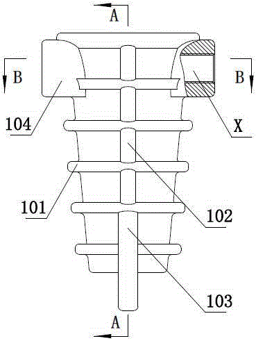
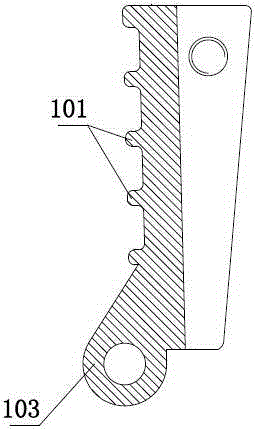
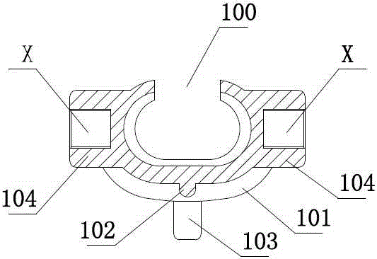
[0027] Such as figure 1 , figure 2 with image 3 As shown, the body of the insulated strain clamp in the prior art is formed by casting aluminum material. After the casting, the insulated strain clamp is as figure 1 Shown is roughly wedge-shaped, for ease of description, with figure 1 The up and down distance in is its height, with figure 2 The left and right distance in is its thickness, with image 3 The upper and lower distance in is its width, and the cross section of the insulation strain clamp is as image 3 It is roughly C-shaped, that is to say, the insulating strain clamp has an inner cavity with an opening 100 on one side, the opening 100 penetrates from the upper part to the lower part thereof, and the outer surface of the insulating strain clamp has multiple transverse ribs 101 and a vertical rib 102, and the bottom of which is provided with protruding lugs 103. The upper two sides of the insulating strain clamp are symmetrically provided with wire clip ears 104. The insulating strain clamp after casting needs Machining the ear 104 of the wire clip, that is, process the threaded blind hole at the ear of the wire clip, figure 1 with image 3 The X-lead in the pointed out that the threaded blind hole is processed and formed. The threaded blind hole is used to connect the pull plate to form an insulating strain clamp assembly for the drainage of the overhead transmission line. When the existing ordinary drilling machine is used for processing, it is necessary Positioning the insulation strain clamp, there is no special tooling for clamping and positioning it. Due to the shape of the insulation strain clamp and the arrangement of the ribs and lugs, the clamping and positioning of the insulation strain clamp is very difficult During machining, it is easy to appear asymmetry in the threaded blind holes of the clip ears on both sides. For example, the threaded blind holes on both sides have different axes, and the threaded blind holes are inclined. When the overhead transmission line is drained The insulating strain clamp cannot realize the above-mentioned functions. Therefore, this traditional processing method results in poor product quality, high rejection rate and low labor efficiency of the insulated strain clamp.
[0028] Figure 4 with Figure 5 An example of an automatic processing equipment for insulating strain clamps is given for the present invention. For convenience of description, Figure 5 The left and right directions in is the longitudinal direction of the device, Figure 5 The left side of is the front of the device, such as Figure 4 to Figure 6 As shown, the automatic processing equipment for insulation strain clamps includes a frame 1, on which is equipped with two clamp guide rails 2 arranged oppositely and extending along the longitudinal direction of the frame. The inner sides of the two clamp guide rails 2 respectively have supporting wires. A track for the ears of the clip and for the sliding of the ears of the clip, the rear of the rack 1 is equipped with a flipping slide that is located between the two clip guides 2 and turns the bottom up when the clip slides forward Bracket 3, turning and sliding bracket 3 includes a support bracket 31 arranged longitudinally along the frame 1 and adapted to the longitudinal opening of the wire clamp. The front end of the support bracket 31 is equipped with a curved arc that gradually extends downward from back to front. The pallet 32. The width of the curved arc pallet 32 is greater than the width of the longitudinal opening of the wire clamp. The upper part of the frame 1 is equipped with a sliding frame 4 that is driven by a power walking mechanism to slide along the longitudinal direction of the frame. The sliding frame 4 is connected with The toggle post 5 is driven by the toggle power mechanism to slide up and down along the sliding frame. The lower end of the toggle post 5 is set to correspond to the ear of the wire clip when it slides down to the lowest end. The sliding frame 4 is equipped with Driven by the compression power device, the pressure plate 6 which moves up and down along the sliding frame and is located between the two wire clamp guide rails. The back of the frame 1 is symmetrically equipped with automatic drilling mechanism and automatic tapping arranged from front to back. Silk agency.
[0029] Such as Figure 7 with Picture 8 As shown, the wire clamp guide rail 2 includes a vertical plate 21 and a flat support plate 22 connected to the inner side of the vertical plate. The inner side of the vertical plate 21 and the upper surface of the flat support plate form a sliding clip ear The track, the track formed by the above structure is an open track, the side of the clip ears slides against the upper surface of the flat plate, and the end face slides against the inner side of the vertical plate, so as to accurately grasp the insulation strain clamp Of course, it is also possible to use a track formed by a sink groove extending outwardly from the inner surface of the wire clamp guide rail 2. The above-mentioned open track can facilitate the operator to see the slippage of the ear of the wire clamp, namely When there is an abnormal slippage, it can be dealt with in time. The vertical plate 21 is provided with a through hole for the drill bit of the automatic drilling mechanism and the tap of the automatic tapping mechanism to pass, and the vertical plate 21 can slide laterally along the frame 1. And it is connected to the frame 1 by a width adjustment and positioning device. The width adjustment and positioning device includes a plurality of width adjustment bolts 7 screwed on the frame 1 and arranged longitudinally along the frame 1, and the inward ends of the width adjustment bolts are connected to On the vertical plate 21, the width adjustment bolt 7 is screwed to drive the vertical plate to slide laterally along the frame, thereby adjusting the distance between the two vertical plates 21, that is, adjusting the width between the two slides to adapt to different Width of insulation strain clamp.
[0030] Such as Figure 5 , Picture 9 with Picture 10 As shown, the sliding frame 4 is slidably connected to the frame 1 in the longitudinal direction, and the power walking mechanism drive includes a walking motor 8 connected to the sliding frame 4, and the frame 1 is equipped with a rack 9 arranged longitudinally, so The power output shaft of the walking motor 8 is equipped with a power gear 10 meshing with the rack 9, and the frame 1 is screwed with multiple height adjustment screws 11 arranged vertically, and the upper part of the multiple height adjustment screws 11 is equipped with a support frame 16. The support frame 16 is equipped with two longitudinally arranged support rails 17, the sliding frame 4 is slidably connected to the support rail 17 through a sliding block, and the rack 9 is vertically slidably connected to the frame 1 through a locking bolt Locked, the height of the sliding frame 4 can be adjusted through the above adjustment, which is suitable for different types of insulated strain clamps. The sliding frame 4 is connected with a sliding support plate 12 that slides vertically along the sliding frame. A total of two pairs of front and rear are provided. Each pair of toggle posts is symmetrically connected to both sides of the sliding support plate 12. The two front and rear toggle posts 5 on the same side are connected by connecting rods as a whole. And are respectively located in front of each pair of toggle posts. The compression power device includes a compression cylinder 13 connected to the sliding support plate 12. The top of the compression plate 6 is dynamically connected to the piston rod of the compression cylinder 13, and the toggle power mechanism includes The power cylinder 14 connected to the sliding frame 4, the sliding support plate 12 and the piston rod of the power cylinder are dynamically connected, and each pair of shifting posts 5 is used to move an insulating strain clamp, that is to say, two at the same time. Insulation strain clamp, which drives one insulation strain clamp at the automatic drilling position and the other at the automatic tapping position, which can greatly improve labor efficiency. The sliding support plate 12 is equipped with a supporting sleeve 15 and the top of the column 5 is moved The lateral sliding connection is in the support sleeve 15 and the support sleeve 15 is screwed with a positioning bolt for positioning the top of the toggle post. The distance between the two toggle posts in each pair can be adjusted to make it suitable for different models Insulation strain clamp.
[0031] Such as Figure 4 , Figure 5 with Figure 7 As shown, the automatic drilling mechanism includes a drilling frame 18 that is connected to the frame 1 and is driven by a drilling pushing mechanism to slide laterally along the frame. Specifically, the drilling frame is connected to the frame through a guide rail and a sliding block. The machine frame is connected with a drilling screw that is horizontally arranged and connected to the drilling feed motor. The drilling frame is connected with a nut screwed on the drilling screw. The drilling frame is equipped with a drill hole. Motor-driven drill bit fixture, the drill bit is connected to the drill bit fixture, the drill bit is rotated by the driving of the drilling motor, and the drill frame slides laterally through the drive of the drilling feed motor to realize the feed of the drill bit, thereby realizing drilling Function; the automatic tapping mechanism frame includes a tapping frame 19 that is connected to the frame 1 and is driven by the tapping pushing mechanism to slide laterally along the frame. Specifically, the tapping frame is connected to the machine through a guide rail and a sliding block. On the frame, the frame is connected with a tapping screw which is arranged horizontally and is dynamically connected with the tapping feed motor. The tapping frame is connected with a nut screwed on the tapping screw. The tapping frame is equipped with a tapping screw. The tap fixture is driven by the thread motor, and the tap is connected to the tap fixture. The tap is rotated by the drive of the tapping motor, and the tapping frame slides laterally through the drive of the tapping feed motor to realize the tapping feed. For the tapping function, the above specific structure is not shown in the figure.
[0032] The state of use of the present invention is as follows: a plurality of cast-shaped insulating strain clamps are placed in sequence between the two clamp guide rails 2, and the opening part of the insulating strain clamp is set backward, making full use of the insulating strain clamp The wire clip ears are arranged symmetrically above, so that the wire clip ears on both sides are respectively located on the rails of the two wire clip guides. The power cylinder 14 on the sliding frame drives the toggle column 5 to slide down, and the toggle column 5 will reach At the back of the ear of the wire clamp, the power gear 10 is driven to rotate by the walking motor 8 to make the sliding frame slide backward, that is, the insulating strain clamp is moved backwards through the toggle column 2 to the position of the automatic drilling mechanism, insulated During the backward sliding process of the tension clamp, it passes through the sliding sliding bracket 3, and while sliding forward, the bottom of the curved supporting plate 32 is turned up, and the two sides of the opening part span across the supporting bracket. On the frame 31, the insulated strain clamp can be placed horizontally and positioned in the left and right positions. Through this arrangement, the structural characteristics of the insulated strain clamp are fully utilized for positioning in the left and right directions, and the dialing action of the toggle post is realized Position the front and back, and then press the power device to drive the pressure plate to slide down and press against the top of the insulation strain clamp, that is, use the clamp guide 2, flip the sliding bracket 3 to make the insulation strain clamp run and turn it flat. At the same time, the precise positioning of the insulation strain clamp is realized by pressing and positioning. After positioning and pressing, the automatic drilling mechanism is used for drilling. At the same time, the above action drives the insulation strain clamp to run backward to the automatic tapping mechanism and To achieve compaction, tapping by an automatic tapping mechanism to form a threaded hole. This automatic processing equipment can automatically process the threaded hole of the clamp ear on the insulation tension clamp, and at the same time, the processing and positioning are accurate, so that The threaded holes on both sides are completely symmetrical (just need to set the above-mentioned automatic drilling mechanism and automatic tapping mechanism to be symmetrical), this kind of automatic processing can effectively avoid the phenomenon of inclined threaded holes.
[0033] Of course, the present invention is not limited by the foregoing embodiments. For those skilled in the art, equivalent changes and component replacements based on the specific structure of the present invention are all within the protection scope of the present invention.