Direct-current brushless vacuum pump

A brushless DC, vacuum pump technology, applied in the field of air compressors, can solve the problems of heavy metal material, complex manufacturing process, low production efficiency, etc., and achieve the effects of weight reduction, simple manufacturing process and high production efficiency

Inactive Publication Date: 2020-07-24
浙江鸿川医疗科技有限公司
View PDF6 Cites 1 Cited by
  • Summary
  • Abstract
  • Description
  • Claims
  • Application Information

AI Technical Summary

Problems solved by technology

[0003] The brushless DC motor vacuum pump of the prior art has the following problems: 1), the cylinder and the valve plate are independent, and a sealing ring is used to seal between the cylinder and the valve plate during assembly, and the sealing ring is a vulnerable part, which is easily damaged and causes air leakage; 2) The left and right cylinder heads are connected by metal pipes, and sealing structures need to be installed at each joint, which is complicated to assemble and easy to leak; 3), the cylinder, cylinder head, box, etc. are cast with aluminum profiles, and the manufacturing process is complicated , high cost, low production efficiency, and high defective rate; at the same time, the metal material is heavy and inconvenient to carry

Method used


Image

  • Direct-current brushless vacuum pump
  • Direct-current brushless vacuum pump
  • Direct-current brushless vacuum pump

Examples


Embodiment

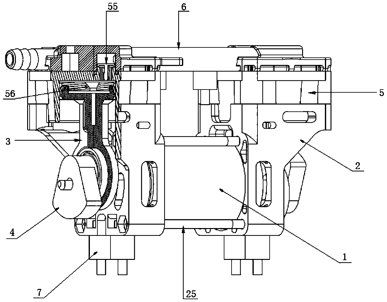
[0030] Examples, combined with Figure 1~6 , a DC brushless vacuum pump, comprising a motor 1, a casing 2, a cylinder connecting rod 3, an eccentric wheel 4, a cylinder 5 and a cylinder head 6, the two ends of the motor 1 are provided with a casing 2, and the cylinder connecting rod 3 and eccentric wheel 4 are sequentially connected symmetrically to both ends of the central axis of the motor 1 and close to the outside of the box body 2 , the upper end of the box body 2 is connected to a cylinder 5 , and the upper end of the cylinder 5 is covered with a cylinder head 6 .

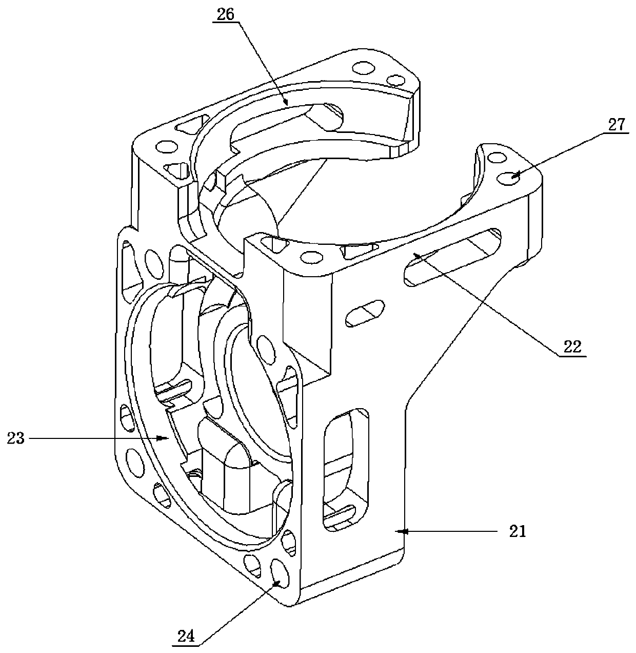
[0031] Described casing 2 comprises motor holder 21 and cylinder holder 22, and described motor holder 21 is a vertical cube, and described motor holder 21 center is provided with motor holder hole 23, and the aperture of described motor holder hole 23 is equal to The outer diameter of the motor 1, the side of the motor holder 21 is provided with a first screw hole 24, the first screw hole 24 is four, the fir...


PUM


Abstract

The invention provides a direct-current brushless vacuum pump. The direct-current brushless vacuum pump comprises a motor, box bodies, air cylinder connecting rods, eccentric wheels, air cylinders andan air cylinder cover; the two ends of the motor are symmetrically sleeved with the box bodies; the air cylinder connecting rods and the eccentric wheels are sequentially and symmetrically connectedat the two ends of a central shaft of the motor and are close to the outer sides of the box bodies; the air cylinders are connected at the upper ends of the box bodies; and the air cylinder cover covers the upper ends of the air cylinders. According to the direct-current brushless vacuum pump, the air cylinders and valve plates are connected in an integrally formed manner, and an air inlet pipe, an air outlet pipe, a cover body I and a cover body II are connected in an integrally formed manner, so that the sealing performance is improved; by the aid of the integrally-formed box bodies providedwith motor fixing seats and air cylinder fixing seats, the motor and the air cylinders are assembled together, so that the assembling efficiency is improved; and modified polyphenyl ether is used forreplacing aluminum profiles, the box bodies, the air cylinders and the air cylinder cover are manufactured by the aid of molds through one-time injection molding, the efficiency is high, the cost islow, and the direct-current brushless vacuum pump has the outstanding insulation performance, water resistance and corrosion resistance and is light in weight and convenient to carry.

Description

technical field [0001] The invention relates to the field of air compressors, in particular to a DC brushless vacuum pump. Background technique [0002] The DC brushless motor vacuum pump is powered by a DC brushless motor, and the circular motion of the motor is used to make the diaphragm inside the pump reciprocate through a mechanical device, thereby compressing and stretching the air in the pump chamber with a fixed volume. Vacuum (negative pressure) creates a pressure difference between the pump suction port and the external atmospheric pressure. Under the action of the pressure difference, the gas is pressed (suctioned) into the pump chamber and then discharged from the exhaust port. [0003] The brushless DC motor vacuum pump of the prior art has the following problems: 1), the cylinder and the valve plate are independent, and a sealing ring is used to seal between the cylinder and the valve plate during assembly, and the sealing ring is a vulnerable part, which is ea...

Claims


Application Information

Patent Timeline
Patent Type & Authority Applications(China)
IPC IPC(8): F04B37/14F04B35/04F04B39/00F04B39/12
CPCF04B35/04F04B37/14F04B39/00F04B39/122F04B39/125
Inventor 谭洪刘斌
Owner 浙江鸿川医疗科技有限公司
Why Eureka
Try Eureka