
Hydraulic inner mould of single-wire box girder

A box girder and hydraulic technology, applied in the direction of molds, etc., can solve the problems of increasing labor intensity, affecting the efficiency of beam making, and difficult to meet the requirements of the stability of prefabricated box girder, achieving fast demoulding speed, convenient use and high production efficiency. Effect

Active Publication Date: 2011-09-14
湖南五新智能科技股份有限公司
View PDF4 Cites 0 Cited by
  • Summary
  • Abstract
  • Description
  • Claims
  • Application Information

AI Technical Summary

Problems solved by technology

The inner cavity of the double-line box girder is wide and short, and the whole machine has good operation stability. The middle section of the inner mold is designed to be 5 pieces, which are connected by hinges, and the integral hydraulic shrinkage is easy to complete; however, the existing single-line single-box single-chamber box The inner cavity of the beam is high and narrow. After the middle section formwork is divided into 5 pieces, it is impossible to realize the integral hydraulic contraction through the connection mode of the hinge. It is necessary to manually disassemble part of the formwork, which increases the labor intensity and affects the efficiency of beam making. The section is the widest and the highest point. According to the traditional section method, the stability of the prefabricated box girder is difficult to meet the requirements

Method used


Image

  • Hydraulic inner mould of single-wire box girder
  • Hydraulic inner mould of single-wire box girder
  • Hydraulic inner mould of single-wire box girder

Examples


Embodiment Construction

[0014] The specific implementation of the device will be described in detail below in conjunction with the accompanying drawings.

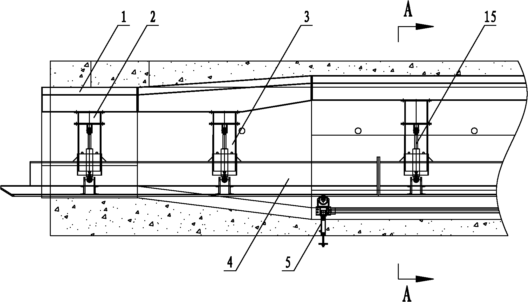
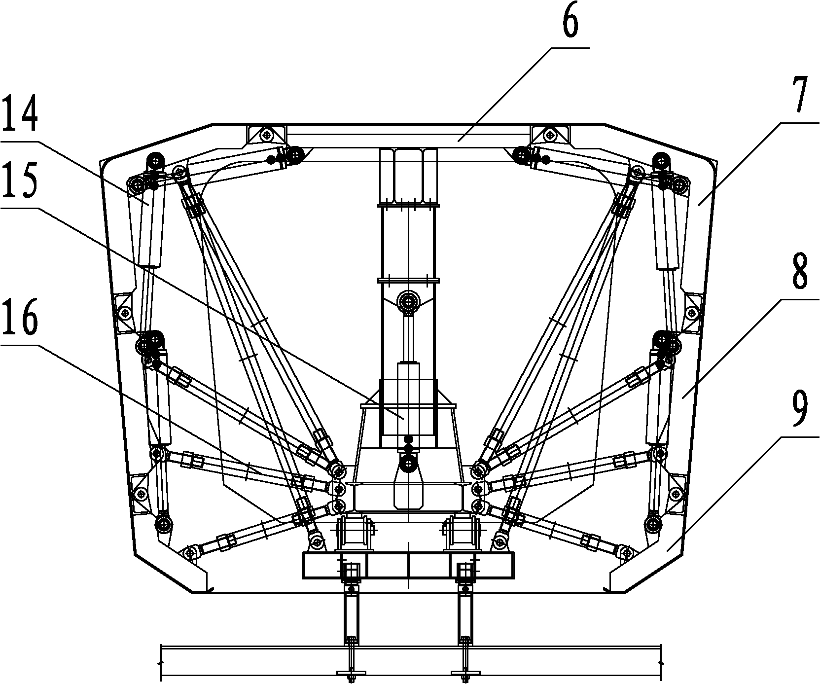
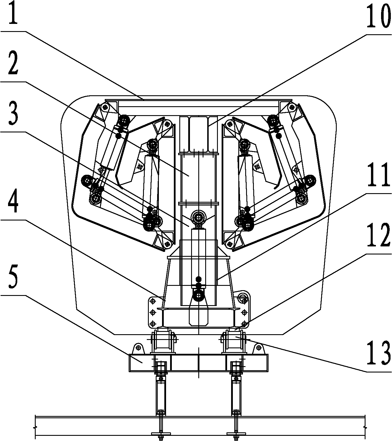
[0015] The single-line box girder hydraulic internal mold provided by the present invention includes a formwork 1, an adjustment column 2, a guide column 3, a main beam 4, a supporting base 5, a lateral oil cylinder 14, a jacking oil cylinder 15 and a telescopic strut 16, wherein the main beam Guide sleeve 11 is installed in 4, and guide rail 12 is equipped with at the bottom of girder 4, and anti-roller 13 is installed on support base 5. The formwork 1 is connected with the guide column 3 through the adjustment column 2. The guide column 3 is installed in the guide sleeve 11 in the main beam 4 and can slide in the guide sleeve 11. The main beam 4 is placed on the support base 5 through the guide rail 12 at the bottom. On the anti-roller 13 and can slide on the anti-roller 13, the internal mold is dragged out of the beam body, and the jacking cyli...


PUM


Abstract

The invention discloses a hydraulic inner mould of a single-wire box girder. The hydraulic inner mould comprises a supporting base, a guide column and a main girder, wherein a guide sleeve is arranged in the main girder; a guide rail is arranged at the bottom; a reverse roller is arranged on the supporting base; the main girder is arranged on the reverse roller of the supporting base by the guide rail; the guide column is arranged in the guide sleeve of the main girder and can slide in the guide sleeve; an adjusting column is arranged above the guide column; a top plate longitudinal girder is arranged on the adjusting column and connected with a top mould; a lifting oil cylinder which drives the top mould to lift and descend is arranged between the main girder and the guide column; an upper movable mould, a first lower movable mould and a second lower movable mould are sequentially arranged in bilateral symmetry of the top mould; the top mould is hinged with the upper movable mould, the upper movable mould is hinged with the first lower movable mould, and the first lower movable mould is hinged with the second lower movable mould; and side oil cylinders are respectively arranged between the top mould and the upper movable mould, between the upper movable mould and the first lower movable mould, and between the first lower movable mould and the second lower movable mould. The hydraulic inner mould of the single-wire box girder is characterized by convenience of operation and use, good moulding quality of the box girder, high de-moulding speed, high production efficiency and the like, and is applicable to box girder inner moulds of the same type.

Description

technical field [0001] The invention relates to a single-line box girder hydraulic internal mold. Background technique [0002] On the high-speed railway passenger dedicated line, in view of the high-standard requirements of high-speed traffic on the smoothness of the line, most road sections are spanned in the form of bridge structures, which makes the hollow prestressed box girders with full holes widely used. In the prefabrication process, one of the necessary large-scale construction equipment is the supporting mold "inner mold" that forms the space inside the box. The length, width and height of the internal formwork are determined by the box girder type, which is divided into double line and single line. The inner cavity of the double-line box girder is wide and short, and the whole machine has good operation stability. The middle section of the inner mold is designed to be 5 pieces, which are connected by hinges, and the integral hydraulic shrinkage is easy to comple...

Claims


Application Information

Patent Timeline
IPC IPC(8): B28B7/22
Inventor 王祥军谢亮夏仙桃张悟
Owner 湖南五新智能科技股份有限公司
Learn More