Hydraulic clamping device with powerful self-locking function

A hydraulic clamping and self-locking technology, used in clamping, workpiece clamping devices, supports, etc., can solve the problems of low bearing capacity, high strength and rigidity requirements, reduced clamping rigidity and precision, etc., to achieve convenient operation, Compact structure, self-locking and reliable effect

Inactive Publication Date: 2015-12-23
JIANGNAN UNIV
View PDF5 Cites 13 Cited by
  • Summary
  • Abstract
  • Description
  • Claims
  • Application Information

AI Technical Summary

Problems solved by technology

However, there are still some problems in engineering practice, which are mainly reflected in two aspects. On the one hand, it is the problem of maintaining pressure. It is very difficult to ensure that the hydraulic system is absolutely leak-free under the condition of long-term impact and heavy load. The way of accumulator, but the accumulator is quite an elastic element, when the load exceeds the design load, the clamping system will give way, reducing the clamping rigidity and precision, and the system has no overload capacity
On the other hand, the force of the clamping element is unreasonable. The piston rod of the swing angle clamping cylinder is subject to bending moment in addition to the tensile force, which requires high strength and rigidity; the hinge support of the lever cylinder is subject to more than twice the pressure. Tension, etc.
In order to reduce the system's requirements for pressure maintenance, there are some self-locking oil cylinders, but some have low carrying capacity, and some self-locking oil circuit control is complicated

Method used


Image

  • Hydraulic clamping device with powerful self-locking function
  • Hydraulic clamping device with powerful self-locking function
  • Hydraulic clamping device with powerful self-locking function

Examples


Embodiment Construction

[0019] The specific implementation manner of the present invention will be described below in conjunction with the accompanying drawings.

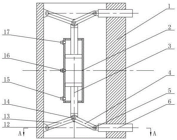
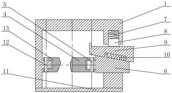
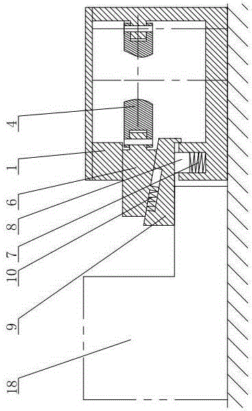
[0020] Such as figure 1 , figure 2 with image 3 As shown, the powerful self-locking hydraulic clamp of this embodiment includes a base body 1, the front end of the base body 1 is provided with a cover body 11, and the upper and lower ends of the side wall of the base body 1 are respectively provided with guiding square holes, which are located in the base body. An oil cylinder 2 is suspended inside the body 1, and a symmetrical piston rod 3 protrudes from the upper and lower ends of the oil cylinder 2 respectively. The head of the piston rod 3 is connected to the front connecting rod 4 and the rear connecting rod 13 through the piston rod pin 14. The rear connecting rod 13 The other end is connected to the hinge seat on the inner wall of the seat body 1 through the hinge pin 12, and the other end of the front connecting rod 4 is connec...


PUM


Abstract

Disclosed is a hydraulic clamping device with a powerful self-locking function. The hydraulic clamping device comprises a base body. A cover body is arranged on the front end face of the base body. Guiding square holes are formed in the upper end and the lower end of one side wall of the base body. An oil cylinder is arranged in the base body in a suspended mode. Piston rods arranged symmetrically extend out from the upper end and the lower end of the oil cylinder respectively. The head of each piston rod is connected with a front connecting rod and a rear connecting rod through a piston rod pin shaft. The other end of each rear connecting rod is connected with a hinged support arranged on the inner wall of the base body through a hinged support pin shaft. The other end of each front connecting rod is connected with an inclined wedge sliding block through a sliding block pin shaft. Each inclined wedge sliding block is connected with an inclined wedge pressing block through a connecting spring in a matched mode. Each inclined wedge sliding block and the corresponding inclined wedge pressing block are installed in the corresponding guiding square hole together. The base body is provided with spring installation holes. Supporting springs are installed in the spring installation holes. Support sliding blocks are installed on the supporting springs. Each support sliding block is pressed on the top surface of the corresponding inclined wedge pressing block. The hydraulic clamping device has a dual mechanical self-locking function of inclined wedge self-locking and connecting rod self-locking, so that the hydraulic clamping device is stable and reliable, and capable of achieving self-locking clamping of clamping force which is greater than 100 tons.

Description

technical field [0001] The invention relates to the technical field of mechanical manufacturing, in particular to a hydraulic clamp with strong self-locking function. Background technique [0002] With the advancement of industrial automation technology, hydraulic clamping systems are used more and more. However, there are still some problems in engineering practice, which are mainly reflected in two aspects. On the one hand, it is the problem of maintaining pressure. It is very difficult to ensure that the hydraulic system is absolutely leak-free under the condition of long-term impact and heavy load. The way of the accumulator, but the accumulator is quite an elastic element. When the load exceeds the design load, the clamping system will give way, reducing the clamping rigidity and precision, and the system has no overload capacity. On the other hand, the force of the clamping element is unreasonable. The piston rod of the swing angle clamping cylinder is subject to bend...

Claims


Application Information

Patent Timeline
Patent Type & Authority Applications(China)
IPC IPC(8): B23Q3/06
CPCB23Q3/08B25B11/00B23Q3/082
Inventor 吕彦明
Owner JIANGNAN UNIV
Why Eureka
Try Eureka