LED support injection molding device with mold positioning device

A technology of LED bracket and positioning device, applied in the field of LED bracket injection molding device, can solve the problems of easy scratching on the surface of the strip, affecting the effect of receiving materials, instability, etc., to prevent jitter, improve processing accuracy, and improve yield. Effect

Inactive Publication Date: 2015-12-23
ANHUI ZHONGZHI LIGHT SOURCE TECH
View PDF0 Cites 4 Cited by
  • Summary
  • Abstract
  • Description
  • Claims
  • Application Information

AI Technical Summary

Problems solved by technology

[0003] The purpose of the present invention is to solve the problem that when the existing injection molding machine is used to make LED brackets, it is unstable in the process of injection molding and receiving materials, and the surface of the strip is easily scratched, thereby affecting the effect of receiving materials

Method used


Image

  • LED support injection molding device with mold positioning device
  • LED support injection molding device with mold positioning device
  • LED support injection molding device with mold positioning device

Examples


Embodiment Construction

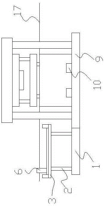
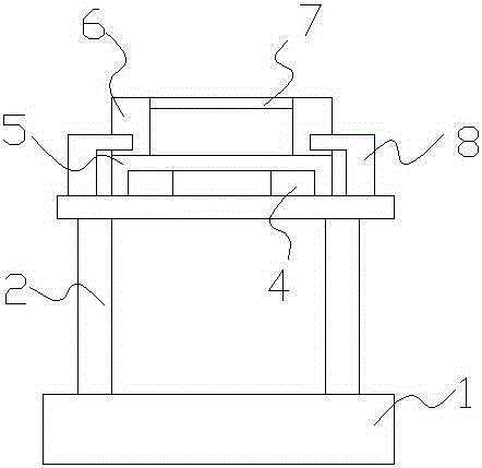
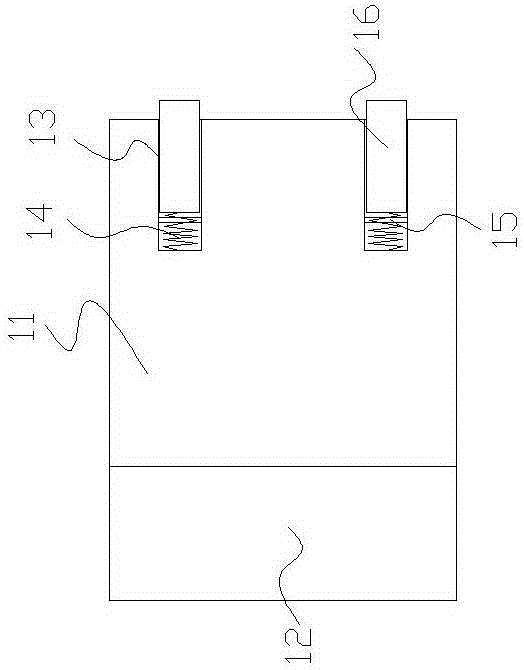
[0011] Combine below figure 1 , 2 , 3, the present invention is described further.

[0012] An LED bracket injection molding device with a mold positioning device, including a feeding device, an injection molding machine, and a material receiving device. The feeding device includes a feeding base plate 1, and a plurality of support rods 2 are arranged on the feeding base plate. The support rods can be telescopic rods, Or a pressure cylinder (such as an air cylinder, an oil cylinder) is fixedly connected on the feed base plate and a through hole matching the support rod 2 is provided on the feed base plate, and one side of the support rod 2 passes through the through hole and is fixedly connected with the piston of the pressure cylinder. The bearing platform 3 is fixedly connected to the supporting rod, and the guide rail 4 is fixedly connected to the bearing platform. The length of the guide rail is adapted to the length of the injection molding machine, and the width is the ...


PUM


Abstract

The invention discloses an LED support injection molding device with a mold positioning device. The LED support injection molding device comprises a feeding device, an injection molding machine and a receiving device; the feeding device comprises a feeding base plate which is provided with a supporting rod, a bearing table is fixedly connected to the supporting rod, a guide rail is fixedly connected to the bearing table, and a clamping base plate is movably connected to the guide rail; two clamping lateral plates are movably connected to the upper surface of the clamping base plate, clamping transverse beams are movably connected between the opposite inner sides of the two claming lateral plates, and limiting plates are movably connected to the positions, on the two sides of the clamping base plate, of the bearing table; the injection molding machine comprises an injection molding machine base plate, and mold positioning blocks are fixedly connected to the two sides of the upper surface of the injection molding machine base plate detachably; each mold positioning block comprises a movable block and a fixed block, a limiting groove is formed in each movable block, a spring is arranged in a groove body of each spring groove, a conduction sheet is arranged on the inner wall of the groove body of each limiting groove, a through hole is formed in the conduction sheet, and limiting blocks are movably connected into the limiting grooves. By means of the structure, the yield is improved.

Description

technical field [0001] The invention relates to an LED bracket injection molding device with a mold positioning device. Background technique [0002] Light-emitting diodes are referred to as LEDs for short, and lamps made of light-emitting diodes are called LED lights. In the process of making LED lights, light-emitting diodes need to be installed on LED brackets. In the process of making LED brackets, injection molding machines need to use molds to perform injection molding on strips. Thereby forming the required shape, when the existing injection molding machine is used to make the LED bracket, it is unstable in the injection molding and feeding process, and the surface of the strip is easily scratched, thereby affecting the product quality. Contents of the invention [0003] The purpose of the present invention is to solve the problem that when the existing injection molding machine is used to make the LED bracket, it is unstable during the injection molding and receivi...

Claims


Application Information

Patent Timeline
Patent Type & Authority Applications(China)
IPC IPC(8): B29C45/26B29C45/17
CPCB29C45/2606B29C45/17
Inventor 汪宗华徐林黄银青周逢海丁宁芮礼文祝雪薇
Owner ANHUI ZHONGZHI LIGHT SOURCE TECH
Why Eureka
Try Eureka