Car bumper device with multiple buffering

A technology for automobile bumpers and buffer devices, applied in bumpers, vehicle parts, transportation and packaging, etc., can solve the problems of increasing manufacturing and installation difficulty, reducing strength, and high cost, so as to improve personal safety, avoid direct collision, principle reliable effect

Active Publication Date: 2015-12-23
来安县永阳知识产权运营有限公司
View PDF9 Cites 15 Cited by
  • Summary
  • Abstract
  • Description
  • Claims
  • Application Information

AI Technical Summary

Problems solved by technology

[0004] In order to overcome the application of patent CN97227448.0, a buffer type automobile bumper is disclosed, which is characterized in that a first-stage shock absorbing system is arranged on the outside of the girder, which are respectively fixed on the front inner wall of the girder and the moving bumper, and the second and third stages are arranged on the inside of the girder. Shock-absorbing system, but the three-stage shock-absorbing system is just a simple structure to increase the number of buffers, which requires a large installation space; some continue to complicate the mechanical structure of the energy-absorbing element to enhance the buffering effect, such as the patent CN201410722933.1 application disclosure An energy-absorbing bumper is developed, which is characterized in that an energy-absorbing element and a telescopic mechanism are installed between the bumper front beam and the bumper rear beam, and the added energy-absorbing elements include shock absorbers and springs, which can jointly enhance the energy-absorbing effect , the patent CN201310202223.1 application discloses a bumper bumper, which is characterized in that the side of the bumper bumper facing the bumper body is grid-shaped, and the bumper bumper is far away from the bumper body. There are mounting components used to connect the mounting brackets. The grid will reduce

Method used


Image

  • Car bumper device with multiple buffering

Examples


Embodiment Construction

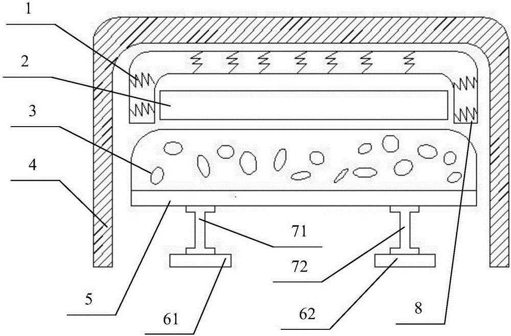
[0009] Below in conjunction with accompanying drawing and embodiment the patent of the present invention is described further.

[0010] Referring to the accompanying drawings, a multi-buffer automobile bumper device includes a buffer spring 1, an anti-collision steel frame 2, an air cavity 3, an outer cover plate 4, a supporting plate 5, a bracket one 61, a bracket two 62, a mounting plate one 71, Mounting plate two 72, connecting frame 8. Wherein, buffer spring 1 is inside connecting frame 8, and connecting frame 8 is plastic material, and it has the effect of absorbing energy, is made of the framework that protects buffer spring 1 by it, reaches the effect of double-layer buffering. The anti-collision steel frame 2 is made of aluminum alloy, and the anti-collision steel frame 2 and the connecting frame 8 are connected by screws (not shown in the figure), which not only has high strength but also meets the requirements of light weight. The filling gas inside the air cavity 3...


PUM


Abstract

The invention discloses a car bumper device with multiple buffering. The car bumper device comprises an outer cover plate, buffering springs, a connection frame, an anti-collision steel frame, gas cavities, a supporting plate, a support and an installation plate. The anti-collision steel frame is made of aluminum alloy. The gas cavities are filled with nitrogen gas and made of a wear-resisting and ageing-resisting rubber material. The buffering springs are clamped inside the connection frame, and the connection frame is made of plastic. The gas cavities are closed among the outer cover plate, the anti-collision steel frame and the supporting plate. A first buffering device comprises the buffering springs and the connection frame, and the reaction force of the buffering springs is utilized for buffering. A second buffering device comprises the anti-collision steel frame providing rigid supporting. A third buffering device comprises the gas cavities, and the air pressure is increased so as to stop further deformation when the gas cavities deform and become smaller. The first buffering device and the third buffering device adopt the energy absorption buffering mode and are supplementary. The second buffering device adopts the supporting buffering mode. The car bumper device is simple in structure and moderate in cost and adopts multiple buffering, and the personal safety of drivers and passengers is high.

Description

Technical field [0001] The invention relates to the technical field of an automobile safety device, in particular to an automobile bumper device with multiple buffers. Background technique [0002] With the development of science and technology and the improvement of people's living standards, more and more cars have entered people's daily life. The bumper belongs to the car safety auxiliary device and is installed at the front and rear of the car body. When a collision occurs, the bumper can protect the vehicle body and prevent the vehicle body from being directly impacted. The national standard "Automobile Front and Rear End Protection Devices (GB17354)" stipulates the specific regulations for low-speed collisions of automobiles. In order to meet this regulation, bumper buffers are used in the bumpers of almost all automobiles. [0003] At present, although the existing bumper has undergone continuous technological updates, it still needs innovation and improvement. The ...

Claims


Application Information

Patent Timeline
IPC IPC(8): B60R19/18B60R19/20
CPCB60R19/18B60R19/20B60R2019/1806
Inventor 刘莉贾文友贾昊瑞高洪周正张志奇李朝晨
Owner 来安县永阳知识产权运营有限公司
Why Eureka
Try Eureka