Anti-vibration device for new energy electric vehicle battery

An electric vehicle and new energy technology, applied in electric vehicles, electric power units, power units, etc., can solve the problems affecting the usability of electric vehicles, affecting the use of batteries, affecting the performance of batteries, etc., to improve stability and use. Long life, safety guarantee, long life effect

Inactive Publication Date: 2019-03-15
吕泽晟
View PDF5 Cites 6 Cited by
  • Summary
  • Abstract
  • Description
  • Claims
  • Application Information

AI Technical Summary

Problems solved by technology

[0002] Electric vehicles are vehicles driven by electric motors. The driving power of electric motors comes from on-board rechargeable batteries or other energy storage devices. As the core component of electric vehicles, batteries are of great importance. The battery box is also essential for installation. The reliability of the installation of the battery box will affect the performance of the battery, which in turn affects the usability of the electric vehicle. When the electric vehicle is driving, due to changes in road conditions, there will be vibrations between the battery box and the battery. In this series of processes, the battery and the battery Various collisions between battery boxes will affect the use of the battery in the long run, and in severe cases, it will cause battery damage

Method used


Image

  • Anti-vibration device for new energy electric vehicle battery
  • Anti-vibration device for new energy electric vehicle battery
  • Anti-vibration device for new energy electric vehicle battery

Examples


Embodiment Construction

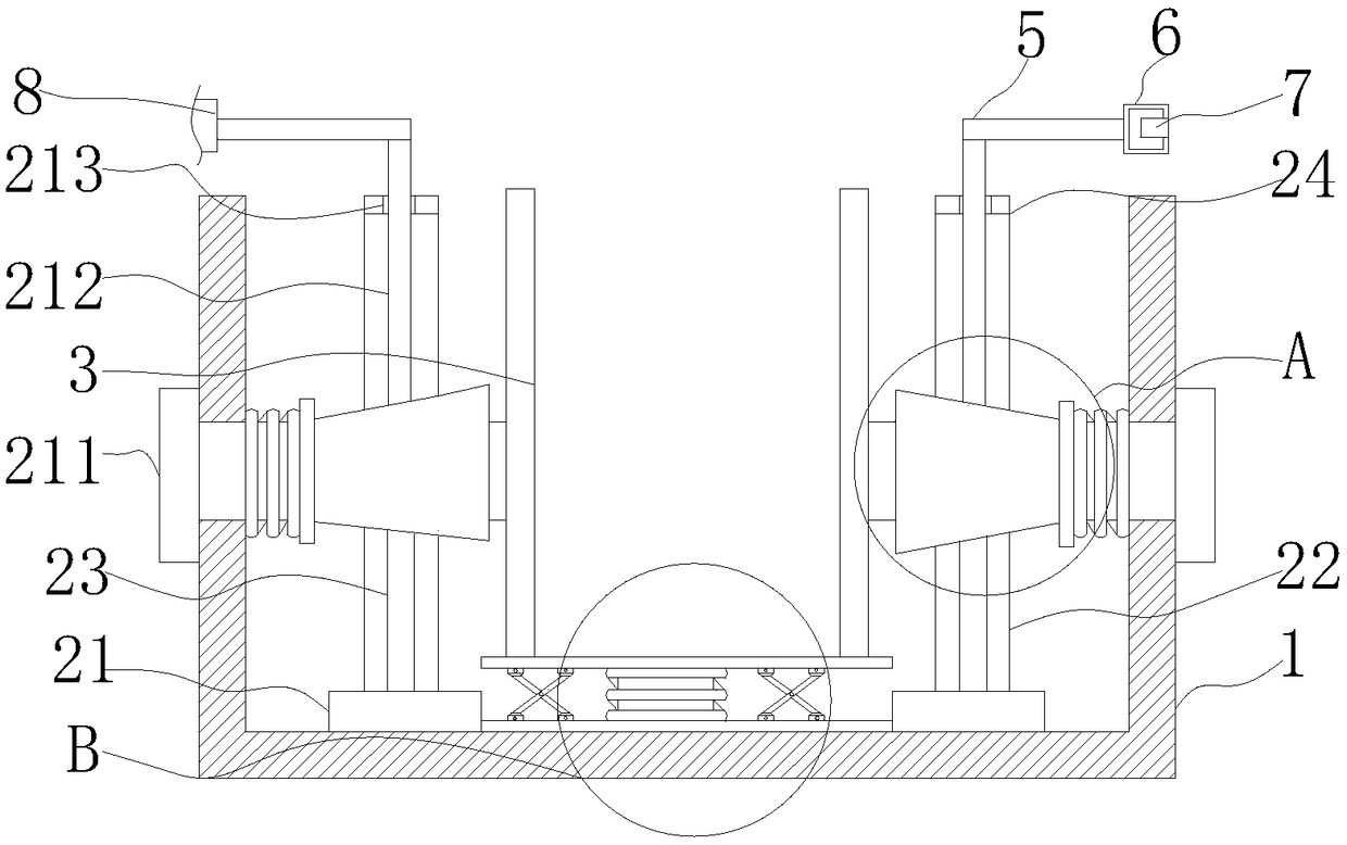
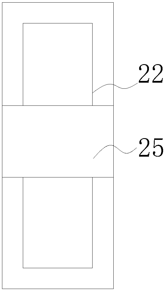
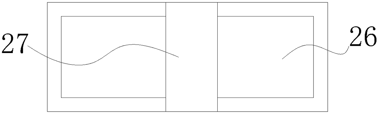
[0031] An embodiment of the present invention provides a new energy electric vehicle battery shock absorber, such as Figure 1-8As shown, it includes a box body 1, two first damping devices 2, two clamping plates 3, a second damping device 4, two clamping plates 5, a clamping block 6, a slot 7 and a clamping device 8 The clamping device 8 includes a fixed box 81, a rotating shaft 82, a gear 83, a sliding groove 84, a sliding rod 85, an inserting rod 86, a turning block 87 and a rack 88. The outer side of the rotating shaft 82 runs through the fixing box 81 and moves with the fixing box 81. Connection, slide groove 84 is offered at the inner bottom of fixed box 81, the inboard of slide groove 84 is slidably connected with the outside of slide bar 85, the top of slide bar 85 is fixedly connected with the bottom of inserting bar 86, fixed box 81, rotating shaft are provided with 82, gear 83, sliding groove 84, sliding bar 85, inserting bar 86, turn block 87 and rack 88, turn turn...


PUM


Abstract

The invention provides an anti-vibration device for a new energy electric vehicle battery, and relates to the technical field of new energy. The anti-vibration device for the new energy electric vehicle battery comprises a box, two first vibration-reduction devices, two clamping plates, a second vibration-reduction device, two clamp plates, a clamping block, a slot and a clamping device. Each first vibration-reduction device comprises a connecting block, a fixing plate, a fixed rod, a connecting plate, a sliding groove, a sliding plate, a notch, a protrusion, a trapezoidal block, an expansionspring, a pulling block, a movable rod, a through opening and a baffle, wherein the bottom of the connecting block is fixedly connected with the internal bottom of the box, the bottom of the fixing plate is fixedly connected with the top of the connecting block, and the bottom of the fixed rod is fixedly connected with the connecting block. By arranging the connecting plates, the sliding grooves,the sliding plates, the expansion springs, the pulling blocks, the movable rods, the through openings and the baffles, the anti-vibration device for the new energy electric vehicle battery solves theproblem that during vehicle driving, the battery easily collides with a battery box, so that the use of the battery is affected.

Description

technical field [0001] The invention relates to the technical field of new energy, in particular to a shock absorber for a battery of a new energy electric vehicle. Background technique [0002] Electric vehicles are vehicles driven by electric motors. The driving power of electric motors comes from on-board rechargeable batteries or other energy storage devices. As the core component of electric vehicles, the battery is self-evident, and the battery box is also essential for installation. The reliability of the installation of the battery box will affect the performance of the battery, which in turn affects the usability of the electric vehicle. When the electric vehicle is driving, due to changes in road conditions, there will be vibrations between the battery box and the battery. In this series of processes, the battery and the battery Various collisions between battery boxes will affect the use of the battery in the long run, and in severe cases, it will cause battery da...

Claims


Application Information

Patent Timeline
Patent Type & Authority Applications(China)
IPC IPC(8): B60L50/64B60K1/04H01M2/10H01M50/249
CPCB60K1/04H01M2220/20H01M50/20Y02T10/70Y02E60/10
Inventor 吕泽晟
Owner 吕泽晟
Why Eureka
Try Eureka