Plane in supersonic speed plane layout

A supersonic and aircraft technology, applied in the direction of wing adjustment, etc., can solve the problems of reduced aerodynamic efficiency, large range of focus position changes, and reduced efficiency of the horizontal tail control rudder surface, etc., to achieve the effect of safe control and high stability

Active Publication Date: 2015-12-23
XIAN AIRCRAFT DESIGN INST OF AVIATION IND OF CHINA
View PDF4 Cites 25 Cited by
  • Summary
  • Abstract
  • Description
  • Claims
  • Application Information

AI Technical Summary

Problems solved by technology

[0003] One is limited by the variable-sweep form, there is more than 45% of the wing area at the root of the wing that cannot be rotated, which largely limits the aerodynamic gains brought by the variable-sweep wing;
[0004] Second, the current variable-sweep wing has only one degree of freedom and requires an ordinary tail
The common empennage has the following disadvantages when controlling the aircraft. Due to the limited area of ​​the rudder surface, a large rudder deflection angle is required to effectively control the aircraft. At this time, large resistance will be generated and the aerodynamic efficiency will be reduced, especially when the aircraft speed is relatively fast. When it is low, the aircraft needs a large angle of attack. At this time, the rudder surface of the vertical tail is deflected to the maximum, which will generate greater resistance
In addition, when the aircraft accelerates from subsonic speed to supersonic speed, the efficiency of the horizontal tail control rudder surface will be significantly reduced, and even the rudder effect will be insufficient;
[0005] Third, due to the wide flight speed range of supersonic aircraft and the wide range of focus position changes, in order to achieve the matching of the focus and the center of gravity of the existing variable-sweep wing aircraft at different speeds, the requirements for the control of the center of gravity of the aircraft are very high. Center of gravity control brings great difficulty

Method used


Image

  • Plane in supersonic speed plane layout
  • Plane in supersonic speed plane layout
  • Plane in supersonic speed plane layout

Examples


Embodiment Construction

[0027] In order to better understand the aircraft according to the supersonic aircraft layout of the program of the present invention, below in conjunction with accompanying drawing ( Figure 1-Figure 8 ) A preferred embodiment of the aircraft of the supersonic aircraft layout of the present invention is further elaborated.

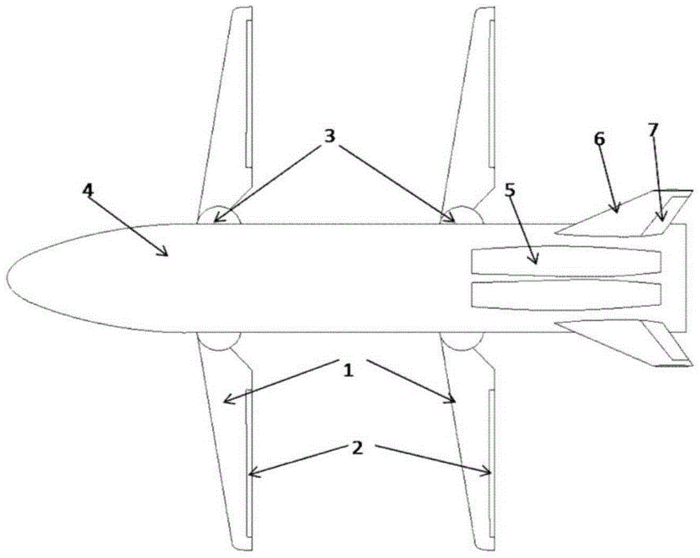
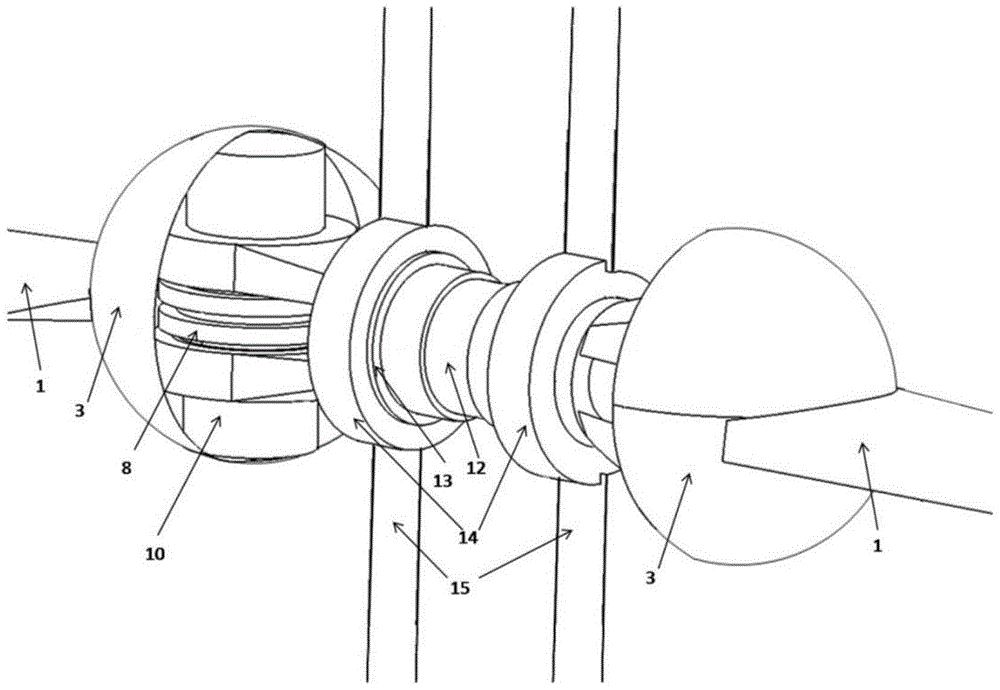
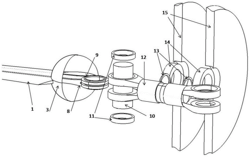
[0028] Such as Figure 1-8 Shown, the aircraft of the supersonic aircraft layout that the present invention provides comprises fuselage 4, wing 1, vertical tail 6, rudder 7, wherein, fuselage 4 both sides are symmetrically arranged with wing 1, and the tail portion of fuselage 4 is symmetrically arranged with Empennage 6, empennage 6 is provided with rudder 7, and fuselage 4 is provided with engine 5, and the head of fuselage 4 is pointed; Wing 1 is a two-degree-of-freedom wing, and wing 1 is connected to fuselage by spherical hinge 3. 4 connected, the wing 1 is provided with a wing control surface 2; the wing control surface 2 is dynamically connected w...


PUM


Abstract

The invention relates to the technical field of plane pneumatic layout design and discloses a plane in a supersonic speed plane layout. Wings are symmetrically arranged on the two sides of a fuselage; empennages are symmetrically arranged on the tail of the fuselage; rudders are arranged on the empennages; an engine is arranged on the fuselage; the head portion of the fuselage is sharp; the wings are two-degree-of-freedom wings and are connected with the fuselage through spherical hinges; wing control surfaces are arranged on the wings; the wing control surfaces are in shaft driving connection with the wings through actuation shafts; the engine is a turbojet engine and is arranged on the rear portion of the fuselage. The plane in the supersonic speed plane layout is provided with the two-degree-of-freedom wings, variable sweepback of the whole wings is achieved, and low-speed, subsonic-speed and supersonic-speed flying can be well considered. According to the demands of different flying states of the plane, efficient and safe control over the plane is achieved by controlling the two degrees of freedom of the wings, stability is high, and the plane is safe and reliable.

Description

technical field [0001] The invention relates to the technical field of aircraft aerodynamic layout design, in particular to an aircraft with supersonic aircraft layout. Background technique [0002] For aircraft design, supersonic cruise has the advantages of fast speed and time saving, while supersonic cruise aircraft often require the aircraft to have a large sweep angle; high subsonic flight has the advantages of faster speed and long range, while high subsonic flight Cruising aircraft often require the aircraft to have a small sweep angle; in addition, the smaller the sweep angle of the aircraft during low-speed take-off and landing, the more conducive to improving the low-speed take-off and landing performance of the aircraft. In order to take into account the performance of supersonic, high subsonic, and low-speed take-off and landing, variable-sweep-wing aircraft represented by B-1B and Tu-160 aircraft have emerged. However, variable-sweep-wing aircraft has the follow...

Claims


Application Information

Patent Timeline
Patent Type & Authority Applications(China)
IPC IPC(8): B64C3/40
Inventor 颉文庆王泽宇吉永刚侯粉段春锴
Owner XIAN AIRCRAFT DESIGN INST OF AVIATION IND OF CHINA
Why Eureka
Try Eureka