Strapping machine

A binding machine and binding wire technology, applied in the field of mechanical packaging, can solve the problems of difficult operation, high labor costs, high cost, etc., and achieve the effect of convenient binding of objects, simple structure and easy operation

Inactive Publication Date: 2015-12-23
屈统撑
View PDF8 Cites 20 Cited by
  • Summary
  • Abstract
  • Description
  • Claims
  • Application Information

AI Technical Summary

Problems solved by technology

Packaging coils through plastic film pairs has the following disadvantages: 1. During transportation, the plastic film is easily damaged due to collisions, friction, etc., resulting in the inability to achieve the packaging effect and affecting the appearance. , it needs to be handled with care, which is very inconvenient; 3. Plastic film is used to pack larger coils, and the cost is higher, so it is not suitable for packing large coils; 3. The structure of the packing machine used for plastic film packing is complex and difficult to operate
Packing the coils with metal wires manually has the following disadvantages: 1. High labor costs; 2. The tightness of the metal wires is not uniform; 3. Low efficiency

Method used


Image

  • Strapping machine
  • Strapping machine
  • Strapping machine

Examples


Embodiment 1

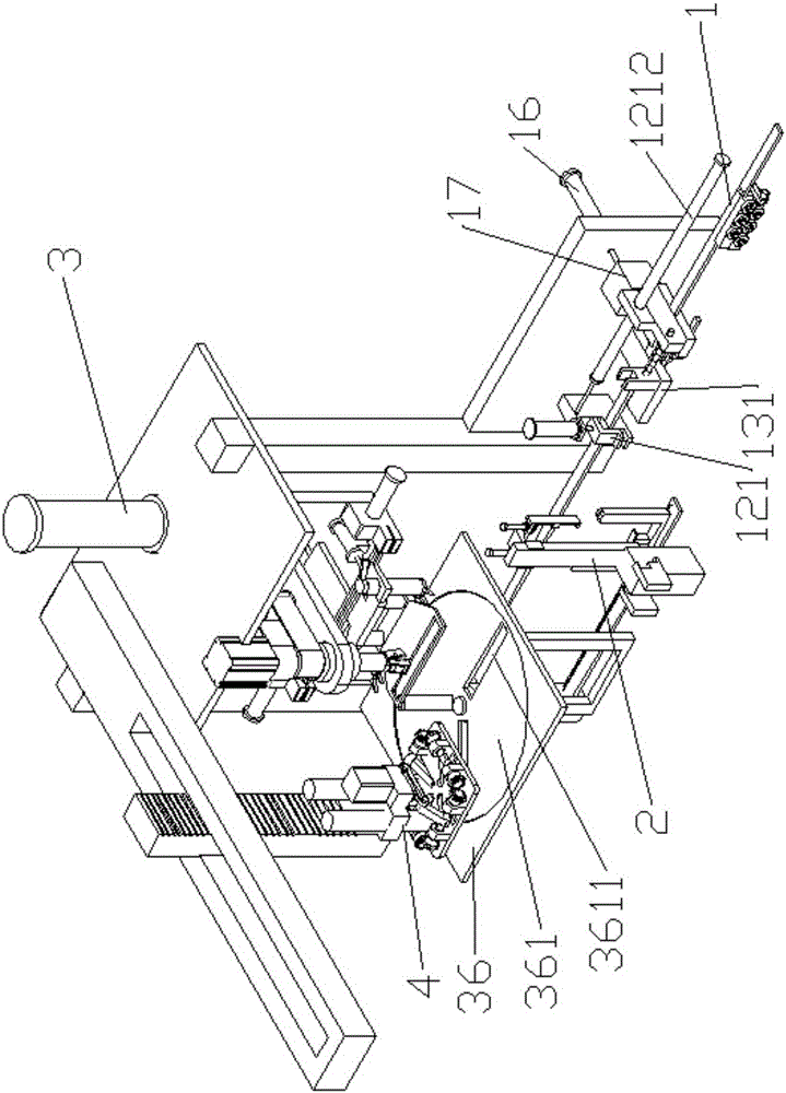
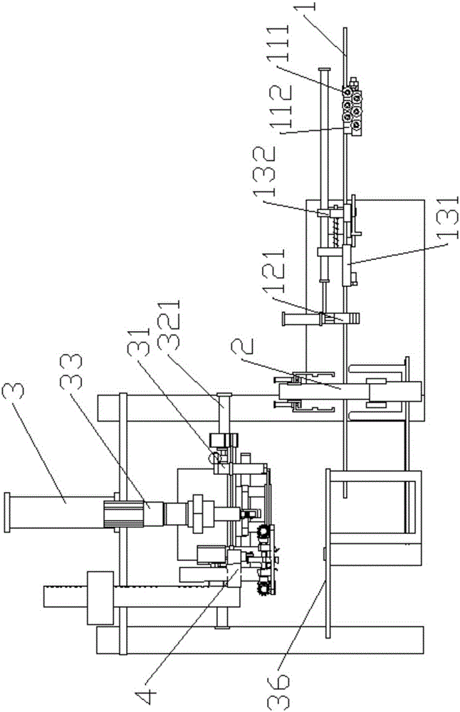
[0064] A strapping machine such as figure 1 , figure 2 , image 3 As shown, it includes a placement table 36 for placing objects to be bundled, a wire feeder 1 for sending the binding wire to the object to be bundled below, and a binding device 3 for binding the objects to be bundled with the binding wire. The device 3 is located above the placement table 36, and the binding device 3 includes two binding clamps 31, a binding lateral movement mechanism 321 for controlling the lateral movement of the two binding clamps 31, a rotating clamp 33 and The rotary mechanism 34 that controls the rotation of the rotary thread gripper 33 , and the two binding thread grippers 31 are respectively located on both sides of the rotary thread gripper 33 .

[0065] In the prior art, metal wires are often used as the binding wires, and the wire feeding device 1 sends the binding wires to the bottom of the strapped objects, and the binding means of the binding device 3 can be the following two ...

Embodiment 2

[0069] On the basis of embodiment one, described embodiment two has been further improved, as figure 1 , figure 2 , image 3 As shown, a U-shaped wire forming device 2 is provided between the binding device 3 and the wire feeding device 1, such as Figure 10 , Figure 11 As shown, the U-shaped wire forming device 2 includes a U-shaped frame 21, a U-shaped frame vertical moving mechanism for vertically moving the U-shaped frame 21, a wire feeding mechanism for sending the wire to the top of the U-shaped frame 21, At least one wire crimping device for clamping and arranged above the U-shaped frame 21 and a wire crimping lifting mechanism 23 for controlling the lifting of the wire crimping device.

[0070] The U-shaped frame 21, as the name implies, generally includes two side bars and a bottom connector for connecting the two side bars. Of course, the U-shaped frame 21 can also be a V-shaped wire forming frame, as long as the two side bars The bottom end can be tilted inwar...

Embodiment 3

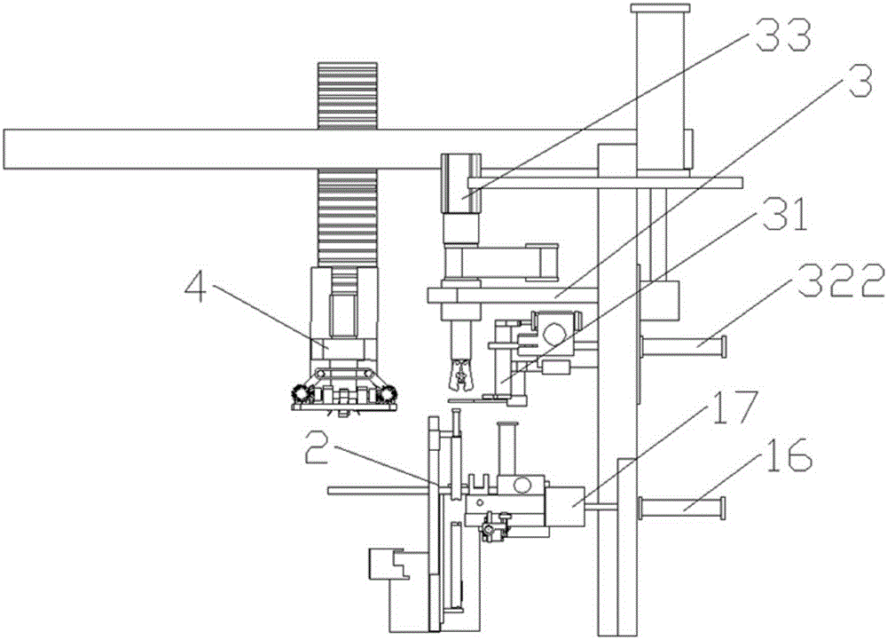
[0075] On the basis of embodiment two, described embodiment three has been further improved, as Image 6 As shown, the binding device 3 also includes a binding longitudinal movement mechanism 322 for controlling the longitudinal movement of the two binding clamps 31 .

[0076] In the U-shaped frame 21, the two ends of the U-shaped wire are higher than the two ends of the U-shaped frame 21, so that the binding clamp 31 can grab the ends of the U-shaped wire. When the U-shaped frame 21 sends the two ends of the U-shaped wire to the top of the object to be bound, if the binding clamp 31 is also just above the U-shaped frame 21, the vertical moving device of the U-shaped frame 21 will During the process of the U-shaped frame 21 sending the thread ends at both ends of the U-shaped wire upward, if the ends of the thread ends do not pass through the clamping range of the binding clamp 31 , the clamping failure will result.

[0077] The binding longitudinal moving mechanism 322 now m...


PUM


Abstract

The invention discloses a strapping machine. The strapping machine comprises a containing table used for containing objects to be strapped, a line feeding device used for feeding a stripping line to the position below the objects to be strapped and a strapping device used for strapping the objects to be strapped through the stripping line. The strapping machine is characterized in that the strapping device is located above the containing table and comprises two strapping line clamping devices, a strapping transverse movement mechanism for controlling the two strapping line clamping devices to transversely move, a rotary line clamping device and a rotary mechanism for controlling the rotary line clamping device to rotate; and the two strapping line clamping devices are located on the two sides of the rotary line clamping device respectively. The strapping machine has the beneficial effects that the structure is simple, and the objects to be strapped, in particular to an annular object, can be strapped through a metal wire.

Description

technical field [0001] The invention relates to the field of mechanical packaging, in particular to a binding machine. Background technique [0002] In the field of machinery, when the processing of the object is completed, the object is often packaged. For example, in the field of coil processing, after the coil is processed, a layer of plastic film is often wrapped on the outside of the coil by mechanical means or the coil is manually wrapped with a metal wire. The coil is packaged by bundling to prevent the coil from being unraveled. Packaging coils through plastic film pairs has the following disadvantages: 1. During transportation, the plastic film is easily damaged due to collisions, friction, etc., resulting in the inability to achieve the packaging effect and affecting the appearance. , it needs to be handled with care, which is very inconvenient; 3. The plastic film is used to pack larger coils, the cost is higher, and it is not suitable for packing large coils; 3....

Claims


Application Information

Patent Timeline
Patent Type & Authority Applications(China)
IPC IPC(8): B65B13/18B65B13/28B65B27/06
CPCB65B13/18B65B13/28B65B27/06
Inventor 屈统撑
Owner 屈统撑
Why Eureka
Try Eureka